Lighting unit

Active Publication Date: 2005-08-18
KOITO MFG CO LTD
View PDF6 Cites 80 Cited by
  • Summary
  • Abstract
  • Description
  • Claims
  • Application Information

AI Technical Summary

Problems solved by technology

Accordingly, there is a related art problem in that it is necessary to eliminate a factor for intercepting a light emitted from the semiconductor light emitting unit, and furthermore, to prevent luminance from being reduced by heat.
Therefore, there is a related art problem in that it is necessary to maintain a relative position with an optical system with higher precision than that in the conventional art to form a light distribution pattern with high precision.

Method used


Image

  • Lighting unit
  • Lighting unit
  • Lighting unit

Examples


Embodiment Construction

[0036] While the invention will be described below with reference to an embodiment of the invention, the following embodiment is not restricted to the invention according to the claims and all of the combinations of features described in the embodiment are not indispensable to means for solving the invention.

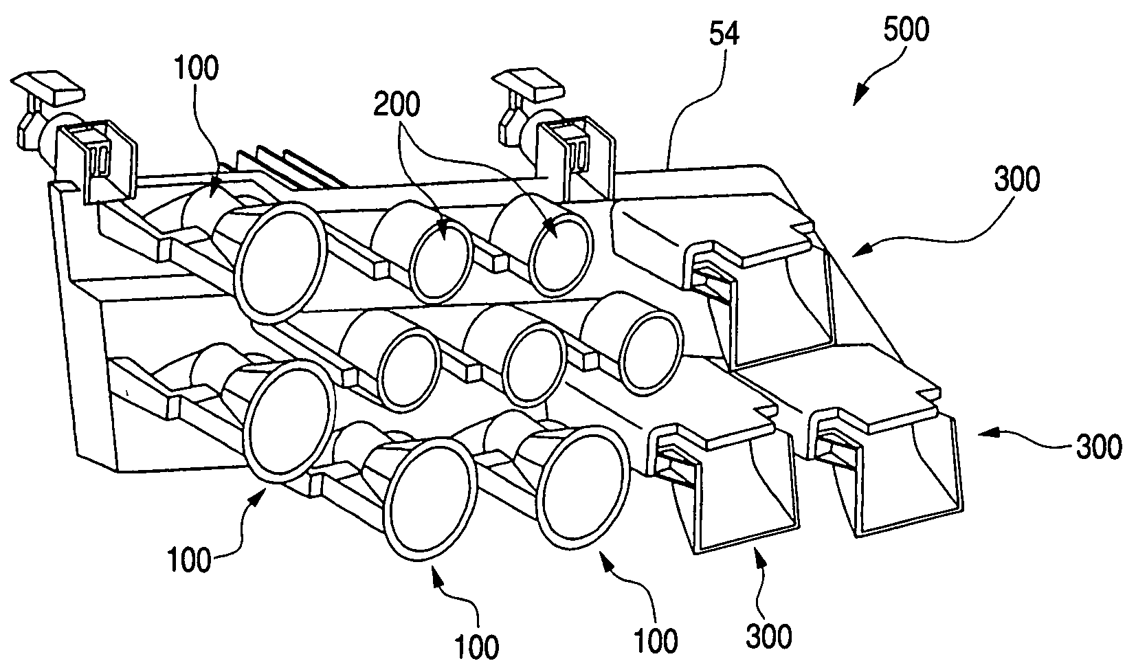
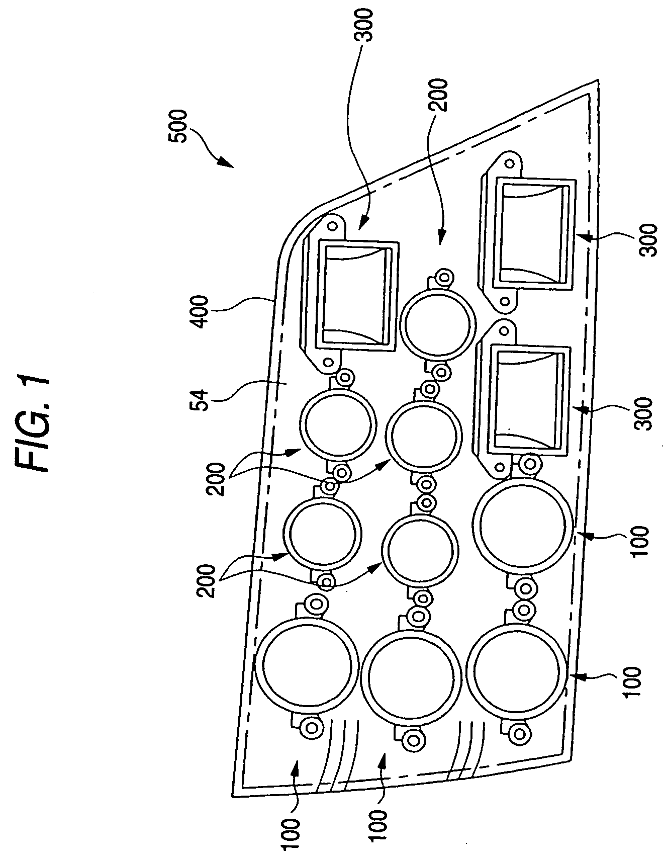
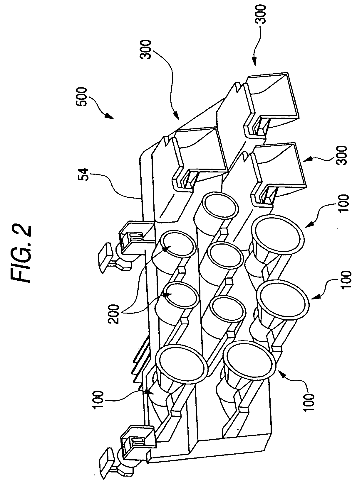
[0037] FIGS. 1 to 3 show an example of the structure of a lighting unit 500 for a vehicle according to an embodiment of the invention. FIG. 1 is a front view showing the lighting unit 500 for a vehicle. FIG. 2 is a perspective view showing the lighting unit 500 for a vehicle in a state in which a cover 400 illustrated in FIG. 1 is removed as seen from an obliquely forward part. FIG. 3 is a perspective view showing the lighting unit 500 for a vehicle illustrated in FIG. 2 as seen from an obliquely rear part. In the embodiment, longitudinal, transverse and vertical directions are substantially coincident with the longitudinal, transverse and vertical directions of the vehicle, re...


PUM


Abstract

A lighting unit for a vehicle includes a light emitting diode unit, a plate-shaped radiating board having an upper surface to which the light emitting diode unit is directly fixed, and a feeding connector connected electrically to the light emitting diode unit at the end of the radiating board and having an input portion for a power to be supplied to the light emitting diode unit below the radiating board. The feeding connector is provided on the end of the radiating board and there may further be provided a wiring extended from the light emitting diode unit toward the end of the radiating board over the upper surface of the radiating board and connected to the feeding connector at the end.

Description

[0001] This application claims foreign priority under 35 USC 119 based on Japanese Patent Application No. 2004-016121, filed on Jan. 23, 2004, the contents of which is incorporated herein by reference. The foreign priority claim is being made concurrently with the filing of this application. BACKGROUND OF THE INVENTION [0002] 1. Technical Field [0003] The present invention relates to a lighting unit. More particularly, the invention relates to a lighting unit using a semiconductor light emitting unit as a light source. [0004] 2. Background Art [0005] In a lighting unit for a vehicle, for example, a headlamp for a vehicle, it is necessary to form a light distribution pattern with high precision in respect of a safety. The light distribution pattern is formed by an optical system using a reflecting mirror or a lens, for example (see JP-A-6-89601 Publication (Pages 3 to 7, FIGS. 1 to 14)). In recent years, it has been investigated to utilize a semiconductor light emitting unit for a li...

Claims


Application Information

Patent Timeline
Patent Type & Authority Applications(United States)
IPC IPC(8): F21S8/12F21S8/10F21V7/06F21V13/00F21V15/01F21V19/00F21V29/00F21W101/10F21Y101/02
CPCF21S48/1104F21S48/1109F21S48/1159F21S48/328F21V19/004F21V29/004H01L2924/0002F21Y2101/02H01L33/62H01L2924/00F21S41/148F21S41/153F21S41/19F21S41/192F21S45/48F21V29/70F21Y2115/10A47J37/0611F24C15/16
Inventor WATANABE, SHIGEYUKITSUKAMOTO, HIRONORI
Owner KOITO MFG CO LTD
Why Eureka
Try Eureka