
Removable optical assembly for a medical instrument

a technology of optical assembly and medical instruments, which is applied in the field of medical endoscopes, can solve the problems of high temperature to crack the adhesive bond and and the risk of significant damage to the endoscope by mechanical force directed at cracking the adhesive bond is high, and the effect of providing fixed optical properties

Inactive Publication Date: 2005-08-18
GYRUS ACMI INC (D B A OLYMPUS SURGICAL TECH AMERICA)
View PDF23 Cites 45 Cited by
  • Summary
  • Abstract
  • Description
  • Claims
  • Application Information

AI Technical Summary

Problems solved by technology

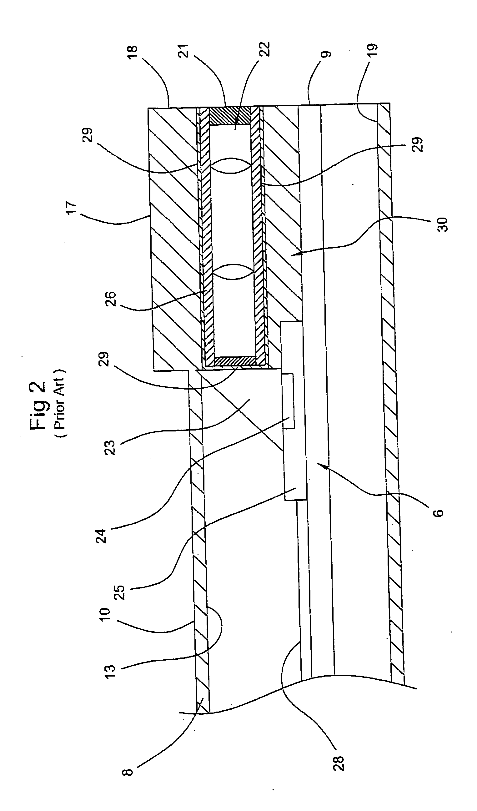
The use of high temperature to crack the adhesive bond can be damaging to the endoscope 2.
Mechanical force directed at cracking the adhesive bond also has a high risk of significant damage to the endoscope 2.
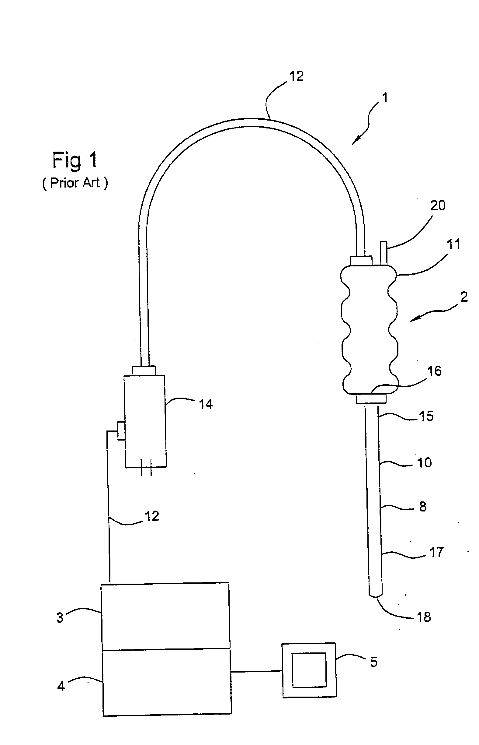
A conventional endoscope 2 has one objective head 30 that is not removable, and therefore, is limited to providing fixed optical properties.
Therefore, it is common that more than one endoscope is used for a particular procedure, leading to increased medical costs.
The increased use of endoscopic diagnostic and treatment procedures is putting a greater burden on the health care industry to contain cost, especially when multiple endoscopes are required, each employing specific optical components suitable for a specific visualization or treatment technique.
Endoscopes are sterilized and reused, but have a finite lifetime requiring eventual disposal of expensive, high precision components.
Attempts have been made to remove the optical elements from the insertion member, but not without having to disassemble major components of the endoscope, risking damaging the components, and enduring time-consuming processes.
This results not only in the issues already mentioned regarding disassembly, but requires a time-consuming process to reassemble and align the lens cell and prism.

Method used


Image

  • Removable optical assembly for a medical instrument
  • Removable optical assembly for a medical instrument
  • Removable optical assembly for a medical instrument

Examples


Embodiment Construction

[0033] In the following detailed description, reference is made to the accompanying drawings that form a part hereof wherein like numerals designate like parts throughout, and in which is shown by way of illustration specific embodiments in which the invention may be practiced. It is to be understood that other embodiments may be utilized and structural or logical changes may be made without departing from the scope of the present invention. Therefore, the following detailed description is not to be taken in a limiting sense, and the scope of the present invention is defined by the appended claims and their equivalents.

[0034] The following embodiments and figures refer to a medical instrument known as an endoscope. The term “endoscope” is used herein a general sense and in accordance with the art, and include, for example, but not limited to, laparoscope, ureteropyeloscope, cystonephroscope, and cystoureteroscope, and medical instruments of substantially similar design. Embodiments...


PUM


Abstract

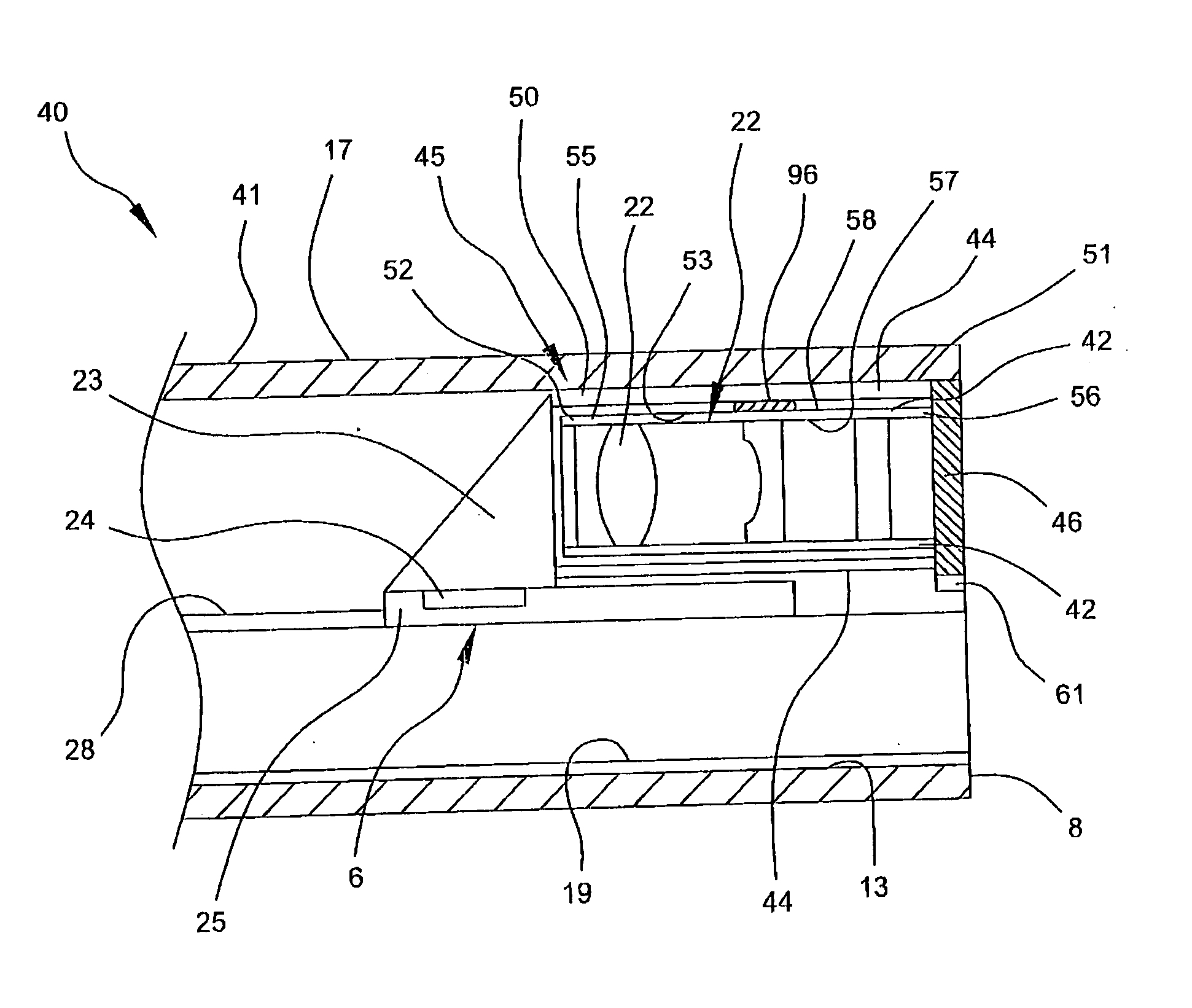
An optical probe, for example, a medical endoscope, having a removable lens cell. In an embodiment, the optical probe has an elongated tube with a proximal portion terminating at a proximal end and a distal portion opposite the proximal portion terminating at a distal end. The elongated tube defines an axial lumen wherein a lens cell holder is disposed proximal the distal portion. The lens cell holder has an axial holder bore for at least partially containing the lens cell within and removably coupled with the holder bore.

Description

RELATED APPLICATION [0001] This application claims priority from PCT Application Serial Number PCT / US03 / 32975 filed Oct. 17, 2003, the contents of which are hereby incorporated by reference as if recited in full herein for all purposes.FIELD OF THE INVENTION [0002] This invention relates to medical endoscopes, and, more specifically, to removable and replaceable optical systems for an endoscope's distal end objective head. BACKGROUND OF INVENTION [0003] An endoscope is a medical device comprising an optical system within an elongated insertion member. Endoscopy refers to procedures wherein an endoscope is used to visualize and / or treat the interior of the body by passing the distal end of the endoscope through an opening or passage. Endoscopes are provided in various configurations suitable for specific procedures. For example, a laparoscope is an endoscope used to visualize and / or treat the interior of the body by passing the distal end of the endo scope through a small incision su...

Claims


Application Information

Patent Timeline
Patent Type & Authority Applications(United States)
IPC IPC(8): A61B1/00A61B1/05A61B1/055A61B1/307G02B23/24G02B23/26
CPCA61B1/00096A61B1/00101G02B23/2423A61B1/307A61B1/05
Inventor D'AMELIO, FRANKKONSTORUM, GREGORYMAZURKEWITZ, ANTHONY
Owner GYRUS ACMI INC (D B A OLYMPUS SURGICAL TECH AMERICA)
Learn More