Door hook with removable spacer

Inactive Publication Date: 2005-09-01
ADAMS MFG
View PDF20 Cites 15 Cited by
  • Summary
  • Abstract
  • Description
  • Claims
  • Application Information

AI Technical Summary

Benefits of technology

[0006] A door hook is provided according to the present invention including a U-shaped metal or plastic bracket having a top member and front and back sides attached to the top member. In a first present preferred embodiment, the front and back sides are separated by a first distance, which corresponds generally to the thickness of the thickest door over which the door hook is intended to be placed. A J-hook is attached to the front side of the U-shaped bracket. A removable spacer is formed as a portion of the back side or at another location on the hook body. A frangible connection is formed in the

Problems solved by technology

When the door is open, a door hook with too wide a top tends to slide and be pulled off the door.
But, it is very difficult to mold thin sections of plastic because plastic does not flow well through thin openings.
Many of these door h

Method used


Image

  • Door hook with removable spacer
  • Door hook with removable spacer
  • Door hook with removable spacer

Examples


first embodiment

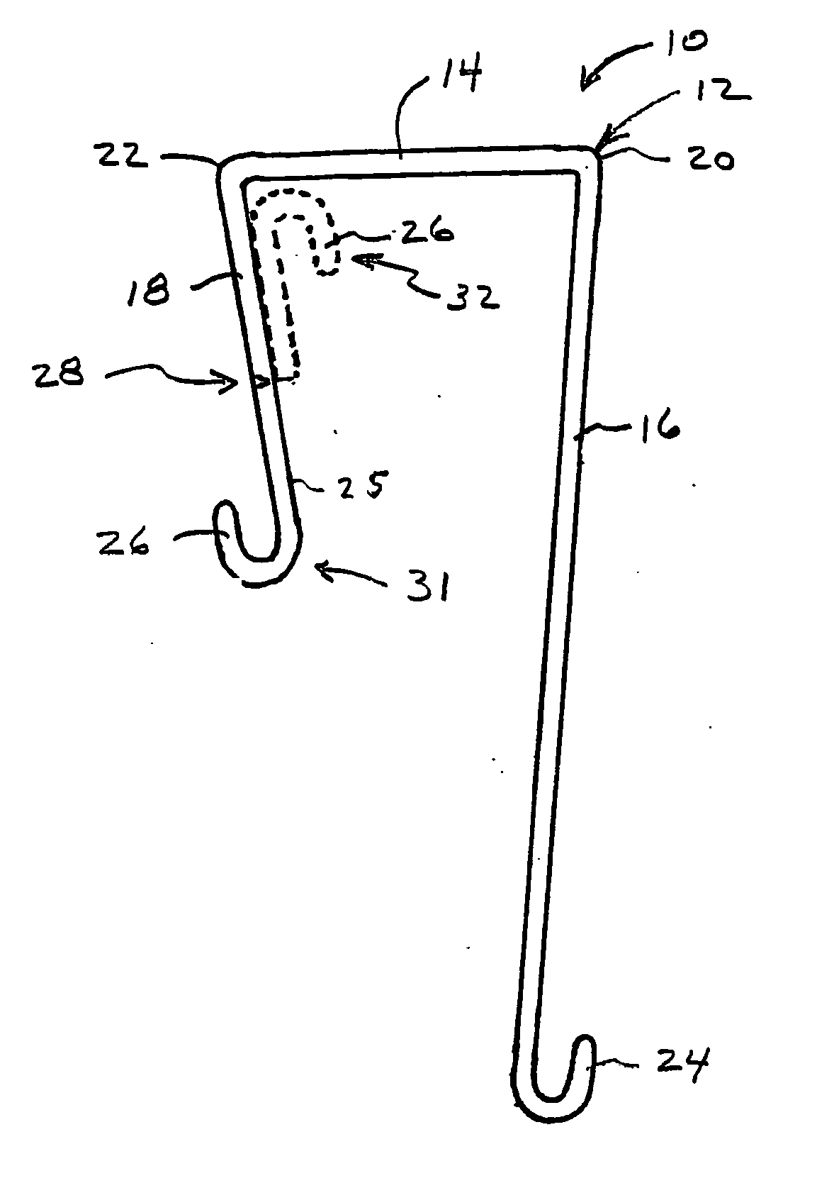
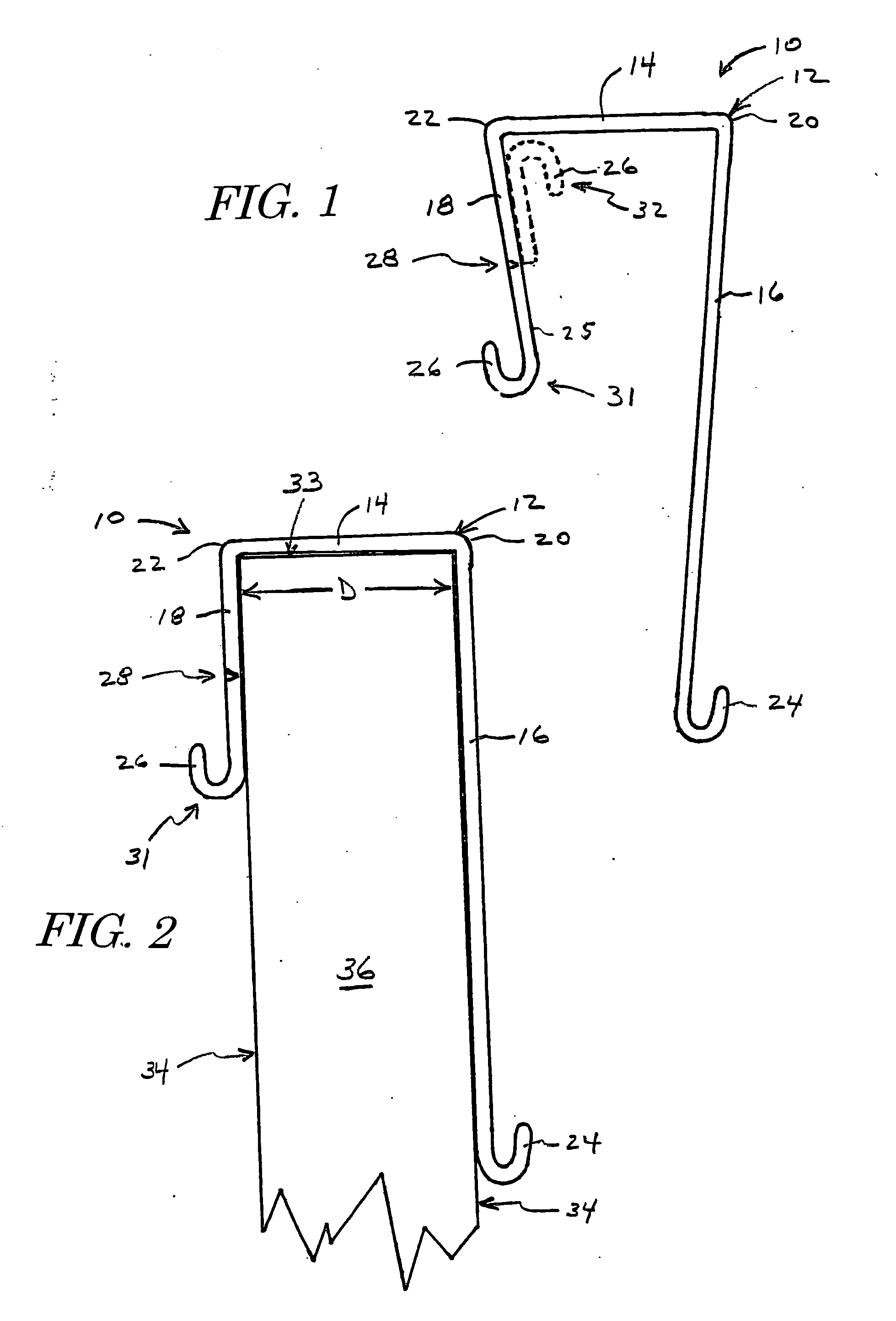
[0028] our over-the-door hook 10 is illustrated in FIGS. 1, 2, and 3. The door hook 10 includes a U-shaped bracket 12 having a top member 14, a front side 16 and a back side 18. The front side 16 is attached to one edge 20 of the top member 14, preferably at an acute angle relative to the top member 14. The back side 18 is attached to an edge 22 of the top member 14 opposite the edge 20 attached to the front side 16. The back side 18 is also preferably attached at an acute angle relative to the top member 14. A hook 24, such as a J-hook, is attached to the front side 16, typically at an end thereof. A spacer portion 26, that may be configured as a J-hook, is detachably connected to the back side 18 by a frangible joint 28.

[0029] The front side 16 and the back side 18 should be at least 1.375 inches long, and the distance between the front side 16 and the back side 18 should be about the same as the thickness of the thickest door on which the hook 10 may be placed. This combination o...

third second embodiment

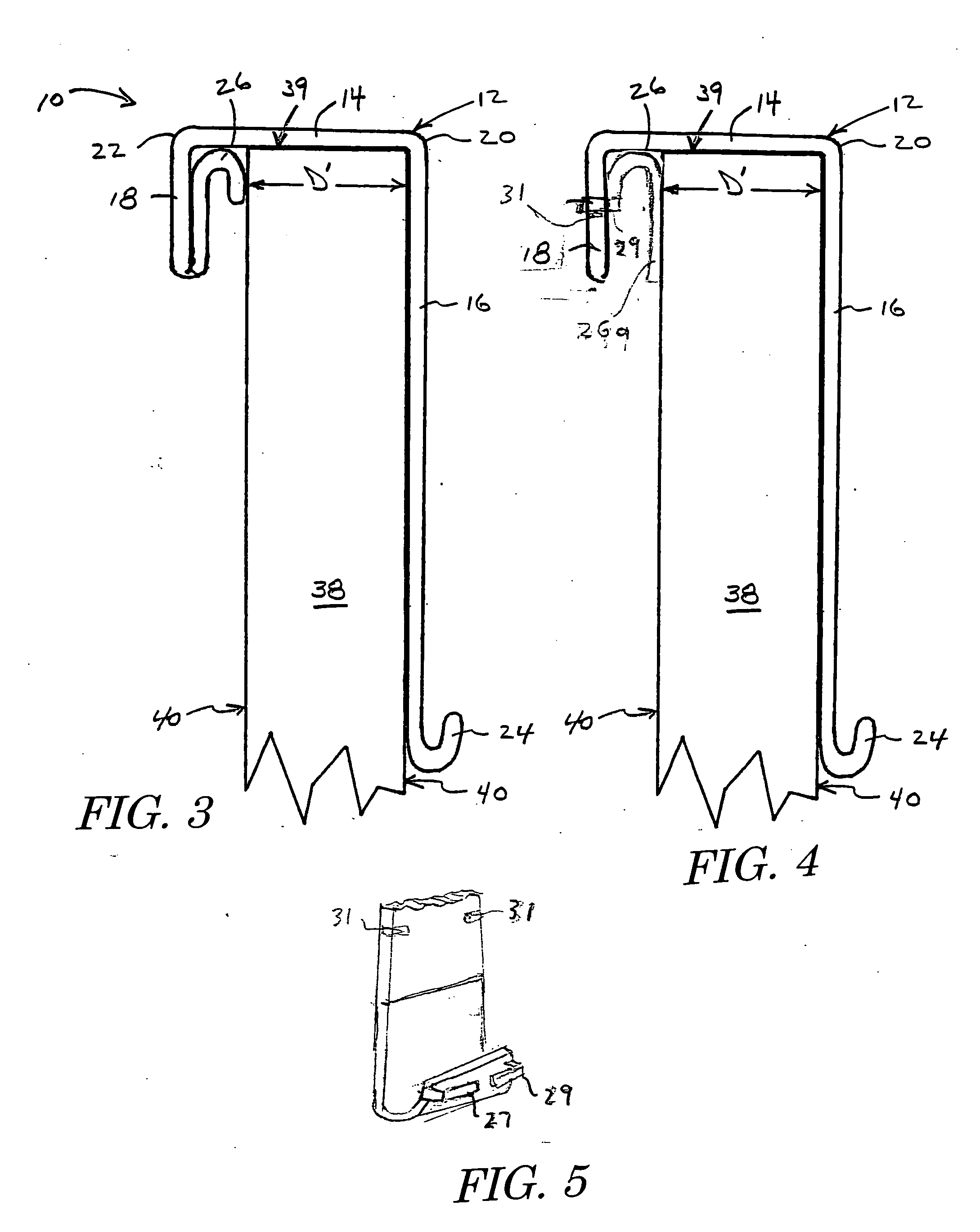
[0036] the present invention is shown in FIG. 6 generally at 41, with like elements of FIGS. 1-3 indicated with the same reference numbers. An additional hook member 42 is attached to the back side 18 of the U-shaped bracket 12. The additional hook member 42 is positioned such that it is between the frangible joint 28 and the edge 22 of the top member 14. In this particular embodiment, with the spacer portion 26 in its original position, the door hook 41 may be snugly fit over the door 36 having a thickness corresponding to the distance D between the front 16 and back 18 sides. Additionally, with the spacer portion 26 in the reattached position, indicated by dotted lines 32, the door hook 41 may be snugly fit over the door 38 having a thickness corresponding to the distance D′ between the spacer portion 26 and the front side 16. In either case, objects may still be attached to the hook 42 provided on the back side 18.

[0037]FIGS. 7 and 8 illustrate further embodiments of the door hoo...

seventh embodiment

[0041] our over-the-door hook 70 illustrated in FIGS. 10 and 11 has a spacer 72 adjacent the back side 78 and projects inward toward the front side 76. Although the spacer is shown as attached to the back side, the spacer could be attached to the top or to both the top and the back side. With the spacer attached, the door hook fits over the thinner door 38. Score lines or serrations 71, 73 are provided in the spacer so that all or a portion of the spacer 72 can be removed. With the spacer portion removed the door hook 70 will fit over a thicker door. If desired that spacer portion could be configured for reattachment to the door hook for use as a spacer or for any other purpose.


PUM


Abstract

A door hook including a U-shaped bracket having a top member and a front side and back side attached to the top member. The front and back sides are separated by a first distance, which corresponds generally to the thickness of a door over which the door hook is to be placed. A hook is attached to the front side, while a spacer portion is attached to the back side or top. A frangible joint is formed in the back side or top such that the spacer portion can be detached and then reattached to the back side. With the spacer portion in this reattached position the spacer portion and the front side are separated by a second distance, different from and typically less than the first-distance. The second distance corresponds generally to the thickness of a thinner or thicker door, over which the door hook may be placed after removal or removal and reattachment of the spacer. In this manner, the door hook may be easily adjusted to fit over doors having different thickness, such as, for example, exterior doors and interior doors. In an alternative embodiment the spacer portion is positioned to fit over a thinner door with the spacer portion in place and over a thicker door when the spacer portion is removed.

Description

FIELD OF THE INVENTION [0001] The present invention is directed toward over-the-door hooks and, more particularly, toward an over-the door hook capable of being used with doors having different thickness. BACKGROUND OF THE INVENTION [0002] There are a variety of hooks that fit over the top of a door. One common type of hook has a U-shaped bracket having an opening not greater than the thickness of the door to which it is to be attached. One or more hooks extend from either or both sides of the bracket. Examples of this type of door hook are disclosed in U.S. Pat. No. 4,817,239 to Campbell et al. and U.S. Pat. No. 6,302,365 to Catanzarite et al. and U.S. Design Pat. No. Des. 342,889 to Adams, U.S. Pat. Des. No. 422,198 to Snell and U.S. Pat. Des. No. 455,947 to Goodman et al. These door hooks are made of plastic or metal and are unitary structures. One shortcoming of this type of hook is that the bracket is sized to fit doors having the same thickness or a slightly smaller thickness ...

Claims


Application Information

Patent Timeline
IPC IPC(8): A45C3/00A47G25/06
CPCA47G25/0614Y10S248/914Y10T16/459Y10T16/4628Y10T16/95
Inventor ADAMS, WILLIAM E.LEMIEUX, GEORGE
Owner ADAMS MFG
Why Eureka
Try Eureka