On-vehicle communication system, optical communication harness and optical distribution apparatus

Inactive Publication Date: 2012-07-26
AUTONETWORKS TECH LTD +2
View PDF31 Cites 16 Cited by
  • Summary
  • Abstract
  • Description
  • Claims
  • Application Information

AI Technical Summary

Benefits of technology

[0049]According to an aspect of the present invention, the optical distribution device can be made with one or more two-input/two-output optical couplers that are relatively inexpensive. Therefore, it is possible to save the cost of the on-vehicle communication system. In an example case that the optical communication is performed between two optical communication apparatuses, one optical coupler is enough for the on-vehicle communication system. In an example case that the optical communication is performed between four optical communication apparatuses, four optical couplers are enough for the on-vehicle communication system. In an example case that the optical communication is performed between eight optical communication apparatuses, twelve optical couplers are enough for the on-vehicle communication system.
[0050]According to an aspect of the present invention, it provides plural optical distribution devices, optical communication lines respectively connected to the plural optical distribution devices, and filters that respectively attenuate light having wavelengths different from wavelengths of optical signals transmitted by optical communication apparatuses that are respectively connected to optical distribution devices. The plural optical distribution devices, optical communication lines and filters are previously connected to form the harness. Therefore, when the harness is connected to optical communication apparatuses, it is possible to easily configure the optical communication system that can perform communication based on the predetermined protocol.
[0051]In the present invention, the filter may be arranged inside a connector that connects a harness and anothe

Problems solved by technology

Thus, each electronic apparatus cannot detect the transmission signal output from itself at the same time when outputting the transmission signal, in the case that the optical communication is utilized for the communication between electronic apparatuses mounted on a car in order to prevent the communication failure caused by the ringing phenomenon, disturbance noise and the like.
In other words, it is not possible to perform the communication based on the conventional CAN protoc

Method used


Image

  • On-vehicle communication system, optical communication harness and optical distribution apparatus
  • On-vehicle communication system, optical communication harness and optical distribution apparatus
  • On-vehicle communication system, optical communication harness and optical distribution apparatus

Examples


embodiment 1

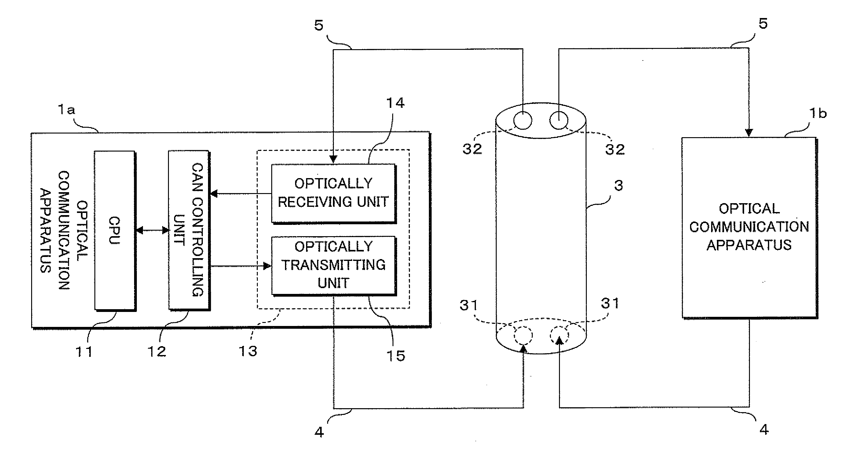
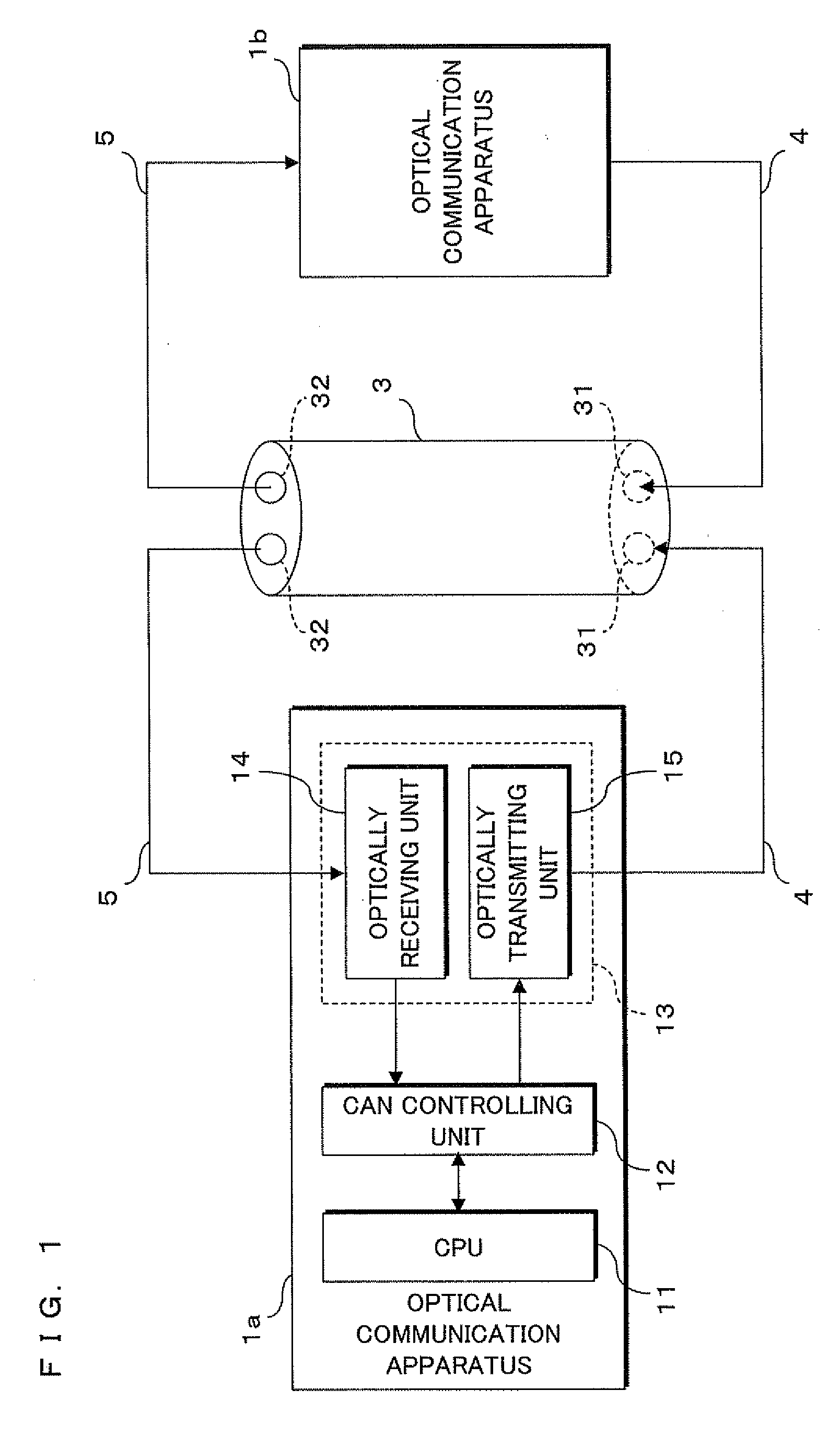
[0070]The present invention will be described in reference to figures that show embodiments according to the present invention. FIG. 1 is a block diagram showing a configuration of an on-vehicle communication system in an embodiment 1 according to the present invention. The on-vehicle communication system in the embodiment 1 is configured with plural (two) optical communication apparatuses 1a, 1b that are respectively connected to an optical coupler 3 through optical communication lines 4, 5, and is a star topology network system where the optical coupler 3 is arranged at the center.

[0071]The optical communication apparatuses 1a, 1b included in the on-vehicle communication system are electronic apparatuses, such as electronic control units (ECUs), which are provided with optical communication functions and mounted on a car (not shown). Although FIG. 1 shows a detailed configuration of the optical communication apparatus 1a, FIG. 1 omits a detailed configuration of another optical co...

embodiment 2

[0089]FIG. 3 and FIG. 4 are block diagrams showing configurations of the on-vehicle communication system in an embodiment 2 according to the present invention. FIG. 3 illustrates an entire configuration of the on-vehicle communication system, and FIG. 4 illustrates a detailed configuration of each component included in the on-vehicle communication system. Although the on-vehicle communication system in the embodiment 1 described above is configured with optical communication apparatuses 1a, 1b that perform only the optical communication, the on-vehicle communication system in the embodiment 2 can perform not only the optical communication but also the electrical communication. The on-vehicle communication system in the embodiment 2 includes two optical communication apparatuses 7a, 7b and one optical coupler 3, similarly to the on-vehicle communication system in the embodiment 1, and further includes four electrical communication apparatuses 9a-9d. It should be noted that the optica...

embodiment 3

[0098]In the on-vehicle communication systems in the embodiments 1 and 2 described above, single two-input / two-output optical coupler 3 is utilized for making two optical communication apparatuses 1a, 1b or 7a, 7b perform optical communication. On the other hand, the on-vehicle communication system in an embodiment 3 can make more optical communication apparatuses perform the optical communication.

[0099]FIG. 5, FIG. 6 and FIG. 7 are schematic views showing example configurations of an optical distribution device utilized for the on-vehicle communication system. FIG. 5 illustrates the two-input / two-output optical couplers 3 utilized by the on-vehicle communication system in the embodiments 1 and 2, although arrows indicate input / output directions of optical signals and the optically inputting unit 31 and optically outputting unit 32 are not shown in FIG. 5. This single optical coupler 3 can make two optical communication apparatuses perform the optical communication, as described in ...


PUM


Abstract

Plural optical communication apparatuses are connected through communication lines with a star topology to an optical coupler that is arranged at the center of star topology and can distribute input light. Each optical communication apparatus makes an optically transmitting unit input an optical signal into an optically inputting unit of the optical coupler, and makes an optically receiving unit receive an optical signal output from an optically outputting unit of the optical coupler, for detecting a collision based on the reception signal. After transmitting an optical signal from the optically transmitting unit, each of optical communication apparatuses makes the optically receiving unit receive the optical signal, performs the collision detection based on the comparison between the transmission signal and the reception signal. When having detected the collision, each of optical communication apparatuses stops own processing for transmitting the optical signal and performs processing for receiving optical signals.

Description

BACKGROUND OF THE INVENTION[0001]1. Field of the Invention[0002]The present invention relates to an on-vehicle communication system that performs communication with plural electronic apparatuses mounted on a vehicle, specifically relates to an on-vehicle communication system that performs optical communication, an optical communication harness and an optical distribution apparatus.[0003]2. Description of Related Art[0004]Many electronic apparatuses are conventionally mounted on a vehicle (e.g., car), and are connected with communication lines to each other. These electronic apparatuses exchange information with each other and work together to control functions regarding travel of the car and to control functions regarding passenger comfort of the car. The controller area network (CAN) is well utilized as the communication standard for implementing the communication with the electronic apparatuses mounted on the car (see non-patent documents 1 and 2).[0005]In addition, it tends to pr...

Claims


Application Information

Patent Timeline
IPC IPC(8): H04B10/08G02B6/293H04B10/272
CPCH04L12/413H04L2012/40215H04L12/44H04B10/272H04L2012/40273H04L12/417
Inventor YUKI, HAYATOUCHINO, TAKEO
Owner AUTONETWORKS TECH LTD
Why Eureka
Try Eureka