Vehicle occupant protection system and inflator

a technology for occupant protection and inflators, which is applied in the direction of vehicle safety belts, pedestrian/occupant safety arrangements, vehicle components, etc., can solve the problems of differential inflation rates of each airbag, unreliable, and prohibitively expensive,

Inactive Publication Date: 2005-09-01
JOYSON SAFETY SYST JAPAN KK
View PDF10 Cites 53 Cited by
  • Summary
  • Abstract
  • Description
  • Claims
  • Application Information

AI Technical Summary

Benefits of technology

[0004] The present invention aims to solve at

Problems solved by technology

One problem with currently available protection systems is that, because each airbag inflation, either the system requires, a) multiple inflators each plumbed to their respective airbags; or b) one inflator plumbed to each airbag.
Sol

Method used


Image

  • Vehicle occupant protection system and inflator
  • Vehicle occupant protection system and inflator
  • Vehicle occupant protection system and inflator

Examples


Embodiment Construction

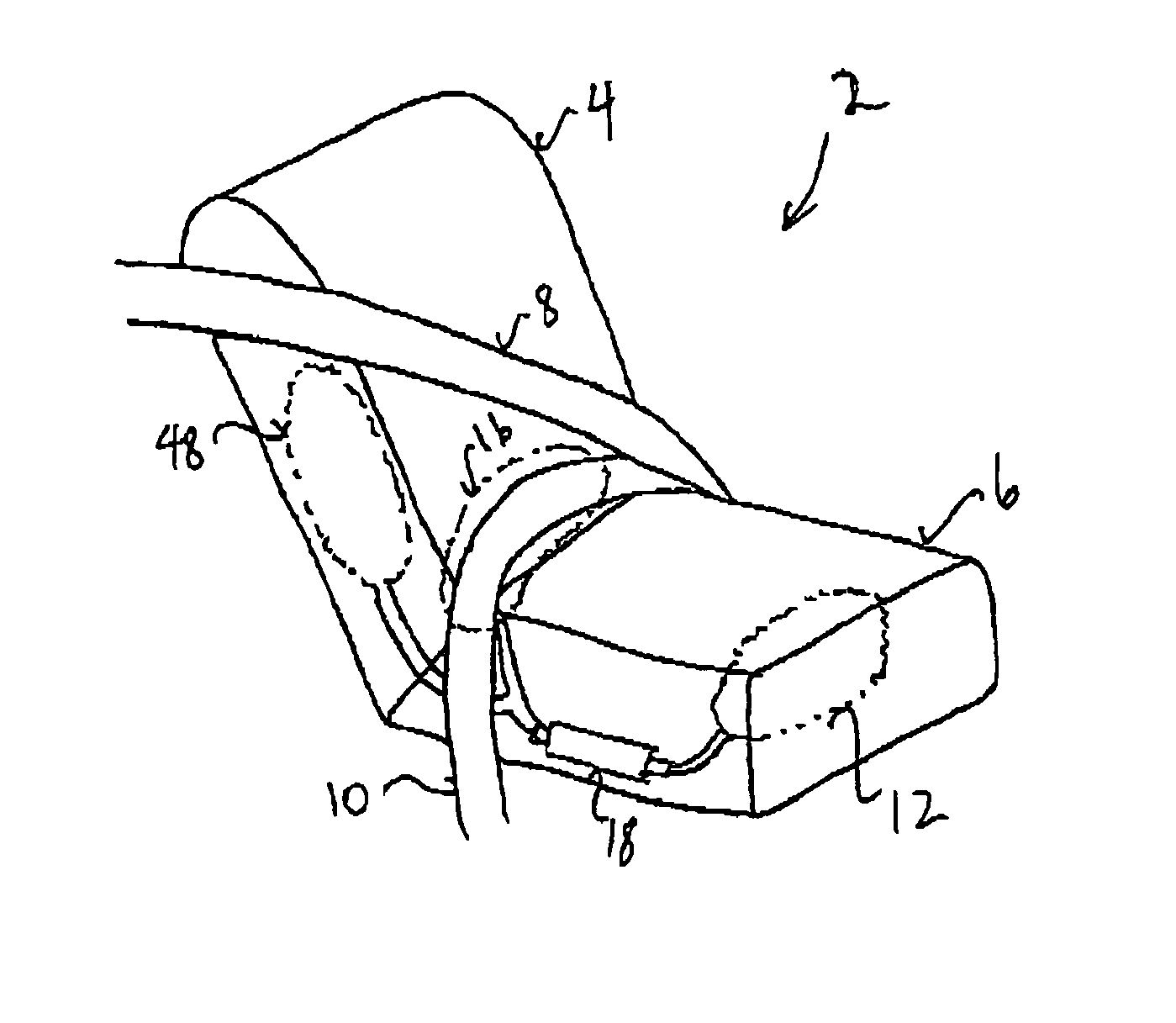
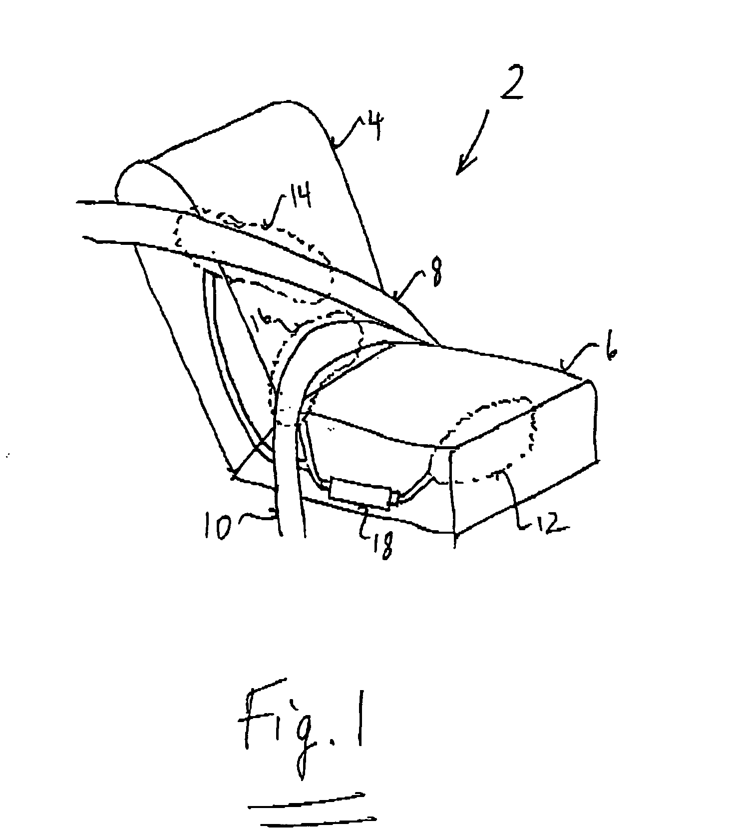
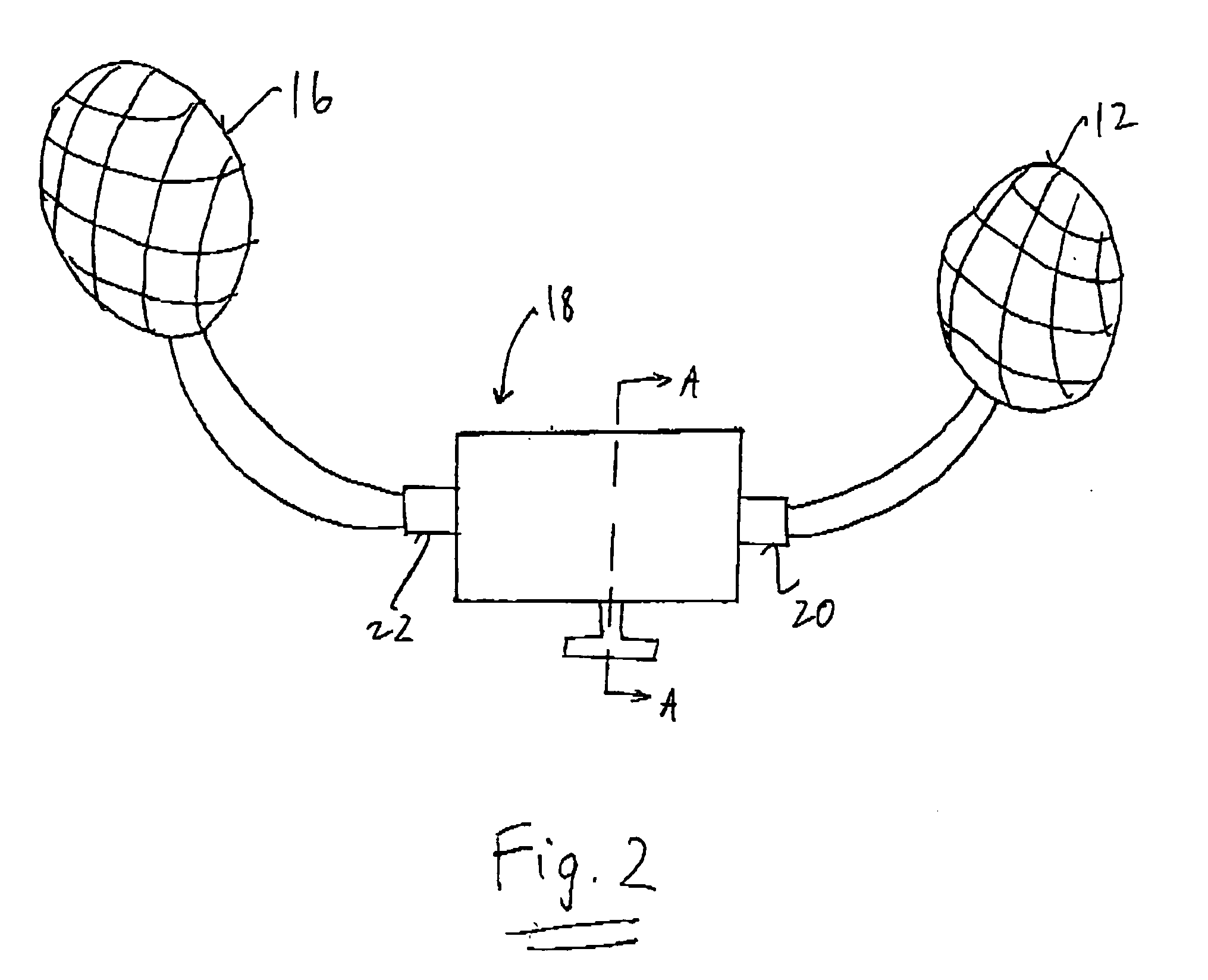
[0029] Referring to FIG. 1, a vehicle occupant protection system comprises a seat 2 having a back rest portion 4 and a bottom rest portion 6, a seat belt having a shoulder belt portion 8 and a lap belt portion 10, a seat airbag 12 connected to the bottom rest portion 6, a shoulder belt airbag 14 connected to the shoulder belt portion 8, a lap belt airbag 16 connected to the lap belt portion 10, and an inflator 18 connected to the airbags 12, 14, 16. The system may also include a seat belt retractor 50 (as shown in FIGS. 8a and 8b) configured to retract and tighten the seat belt 8, 10 when actuated by a high pressure gas (such as from a pyrotechnic gas generator or a high-pressure gas tank). The system may also include a side air bag 48 (as shown in FIG. 7) located within a side of the back rest portion 4 or with a vehicle passenger side door (not shown).

[0030] The seat airbag 12 is preferably located within or underneath bottom rest portion 6, and is configured to cause an upper po...


PUM


Abstract

An inflator having at least first and second gas outputs and configured to generate gas. The inflator releases the gas through the first gas output with a fist gas flow rats and to release the gas through the second gas output with a second gas flow rate different from the first gas flow rate.

Description

CROSS REFERENCE TO RELATED APPLICATIONS [0001] This application claims priority to and the benefit of U.S. Provisional Application No. 60 / 547,807, filed Feb. 27, 2004.[0002] Many vehicle occupant protections systems currently exist, including seat belts, front airbags, side airbags, head side airbags, seat airbags and seat belt airbags (such as lap belt air bags ad shoulder belt air bags). For example, Japanese Patent Publication No. 2003-312439 (Incorporated by reference herein) discloses a seat belt comprising a shoulder belt potion having an inflatable airbag BG1 and a lap belt portion having am inflatable airbag BG2. [0003] Typically, airbags are inflated use either a pyrotechnic inflator and / or a high-pressure gas cylinder. One problem with currently available protection systems is that, because each airbag inflation, either the system requires, a) multiple inflators each plumbed to their respective airbags; or b) one inflator plumbed to each airbag. Solution a) may be prohibit...

Claims


Application Information

Patent Timeline
IPC IPC(8): B60R22/14B60R21/16B60R21/18B60R21/207B60R21/231B60R21/233B60R21/26B60R21/261B60R21/264B60R22/195B60R22/46
CPCB60R21/18B60R21/207B60R21/231B60R2021/2615B60R22/1955B60R2021/23107B60R2021/26094B60R22/1952
Inventor ITOGA, YASUOYOSHIKAWA, HIROMICHIKUMAGAI, MASAYOSHI
Owner JOYSON SAFETY SYST JAPAN KK
Why Eureka
Try Eureka