
Bistable rotary solenoid

a rotary solenoid and rotary solenoid technology, applied in the direction of magnetic bodies, electromagnets with armatures, dynamo-electric machines, etc., can solve the problems of inability to provide constant electrical energy required to keep the shaft in this position, and inability to provide equal torque in both directions

Inactive Publication Date: 2005-09-01
PRACTICAL AUTOMATION
View PDF27 Cites 12 Cited by
  • Summary
  • Abstract
  • Description
  • Claims
  • Application Information

AI Technical Summary

Benefits of technology

[0010] In one embodiment, the rotary solenoid is used in an image enhancement device comprising: a sensor responsive to thermal energy; a shutter movable between a first position and a second position, the shutter allowing the passage of the thermal energy to the sensor in the second position and blocking the passage of thermal energy to the sensor in the first position; with the rotary solenoid coupled to the shutter for driving t

Problems solved by technology

In this type of prior art rotary solenoid it is difficult to provide equal torque in both directions since electromagnetism is the motive power in one direction and resilient energy is the motive power in the other direction.
While such operation is advantageous for some applications, in applications where the shaft must be positioned against the spring bias for long periods of time, the constant electrical energy required to keep the shaft in this position can drain electrical power.
However, the use of mechanical detents or two windings results in a structure that is relatively heavy, bulky, and expensive in relation to the single winding, spring returned type.
However, while the solenoid described in the '175 application is bistable, it is not sufficiently compact for applications where the solenoid must be included in small, portable devices.

Method used


Image

  • Bistable rotary solenoid
  • Bistable rotary solenoid
  • Bistable rotary solenoid

Examples


Embodiment Construction

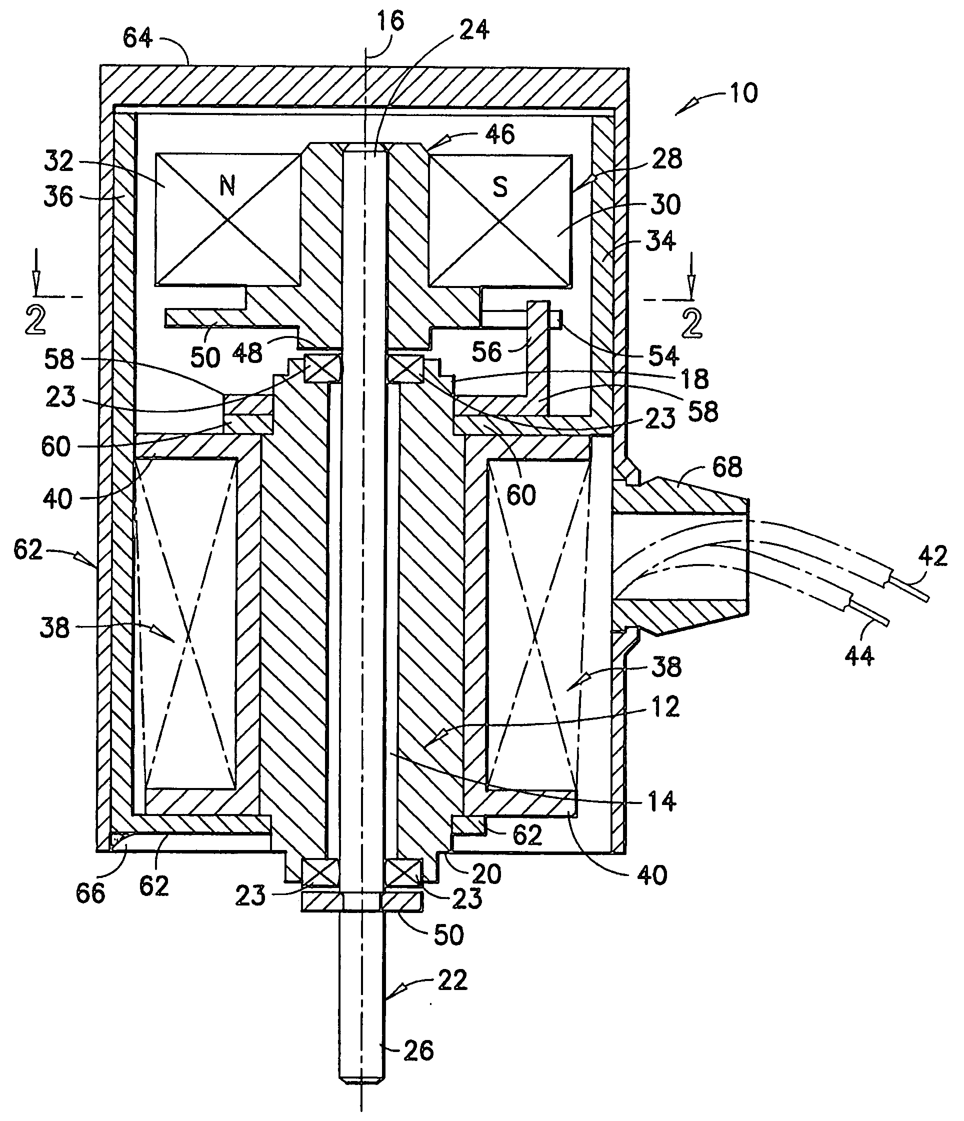
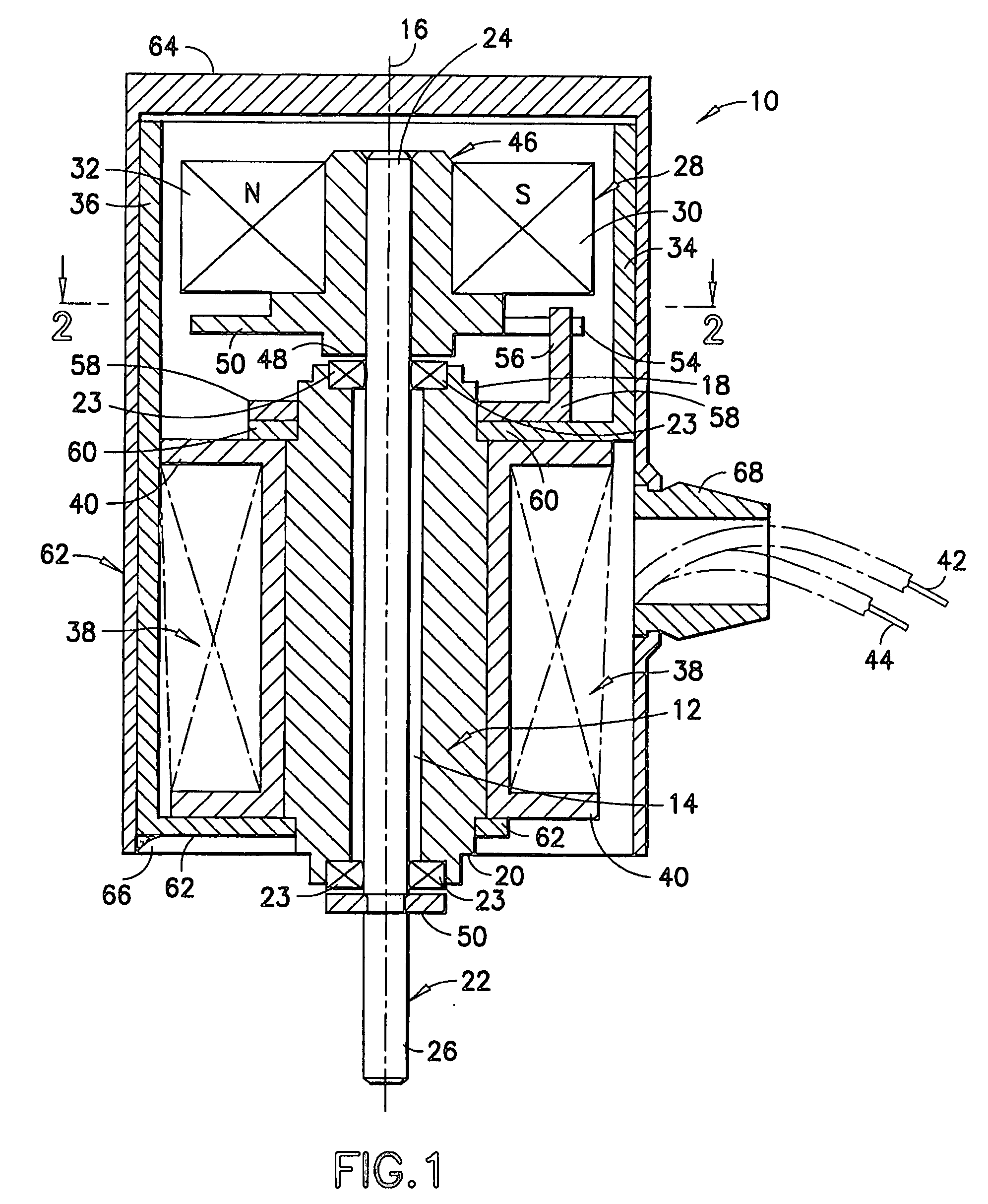
[0017] Referring to FIG. 1, a bistable rotary solenoid is shown generally at 10. The solenoid 10 includes a ferromagnetic core 12 having an aperture 14 disposed along its longitudinal axis 16. The core 12 has a first end 18 and an opposing second end 20. A shaft 22 extends through the aperture 14 and coaxially aligned with the ferromagnetic core 12. The shaft 22 may be supported within the aperture 14 by bearings 23, which allow the shaft 22 to rotate about the longitudinal axis 16 relative to the core 12 while maintaining coaxial alignment between the core 12 and shaft 22. The rotatable shaft 22 has a first end 24 extending outward from the first end 18 of the ferromagnetic core 12 and a second end 26 extending outward from the second end 20 of the ferromagnetic core 12. A permanently magnetized armature 28 is fixedly mounted relative to the first end 24 of the shaft 22 such that the armature 28 and shaft 22 rotate as one. The armature 28 includes a pair of pole portions 30, 32 of ...


PUM


Abstract

A rotary solenoid comprises: a ferromagnetic core having a rotatable shaft disposed through an axial aperture in the core; a permanently magnetized armature fixedly mounted relative to a first end of the shaft, the armature having a pair of pole portions of opposite magnetic polarity; a first stator pole coupled to the first end of the core and extending proximate the armature; a second stator pole coupled to the second end of the core and extending proximate the armature; and a winding disposed around the core, wherein the rotor rotates from a first position to a second position in response to a direct electrical current in a first direction through the winding, and the rotor rotates from the second position to the first position in response to a direct current in a second direction through the winding. The first and second stator poles may be curved around the outer circumference of armature and spaced apart therefrom. A plate may be fixed relative to one of the rotor and the core and a protrusion fixed relative to the other of the rotor and the core, wherein the protrusion is received within a slot disposed in the plate for defining the angle of rotation between the first and second positions. The rotary solenoid may be used in an image enhancement device such as a night and low-light vision device or a thermal imaging device for driving a shutter between open and closed positions.

Description

CROSS-REFERENCE TO RELATED APPLICATIONS [0001] This application claims the benefit of U.S. Provisional Patent Application No. 60 / 540,303 filed Jan. 29, 2004 and entitled “Bistable Rotary Solenoid”, which is incorporated by reference herein in its entirety.BACKGROUND OF THE INVENTION [0002] 1. Field of the Invention [0003] This invention relates to rotary solenoids. More specifically, this invention relates to bistable rotary solenoids. [0004] 2. Description of the Related Art [0005] In rotary solenoids, electrically energizing a winding produces movement of a shaft. In certain prior art rotary solenoids magnetic attraction generated by energizing the winding attracts an armature to move the shaft in one direction and tensions a coil spring which moves the shaft in the other direction when the winding is deenergized. In this type of prior art rotary solenoid it is difficult to provide equal torque in both directions since electromagnetism is the motive power in one direction and resi...

Claims


Application Information

Patent Timeline
IPC IPC(8): H01F7/08H01F7/18H02K26/00
CPCH02K26/00
Inventor BRODT, PHILIPPDESAI, DHAVAL R.
Owner PRACTICAL AUTOMATION
Features
  • Generate Ideas
  • Intellectual Property
  • Life Sciences
  • Materials
  • Tech Scout
  • Unparalleled Data Quality
  • Higher Quality Content
  • 60% Fewer Hallucinations
Learn More