System and method for position determination

a position determination and position technology, applied in the field of position determination, can solve the problems of high and unacceptable noticeable, inconvenient to use, and high visual perceptibility

Inactive Publication Date: 2005-09-01
BRITISH BROADCASTING CORP
View PDF5 Cites 214 Cited by
  • Summary
  • Abstract
  • Description
  • Claims
  • Application Information

AI Technical Summary

Benefits of technology

[0009] It is an object of at least preferred embodiments of this invention to provide a means of measuring the motion of a camera in real-time without the need for incorporating special markers in the scene, and

Problems solved by technology

In particular, certain types of error in position may be highly and unacceptably noticeable, as they can lead to visually highly perceptible effects.
For example, a position determination method which provides a position with a relatively small but randomly fluctuating error may be perfectly usable for most purposes but may give

Method used


Image

  • System and method for position determination
  • System and method for position determination

Examples


Embodiment Construction

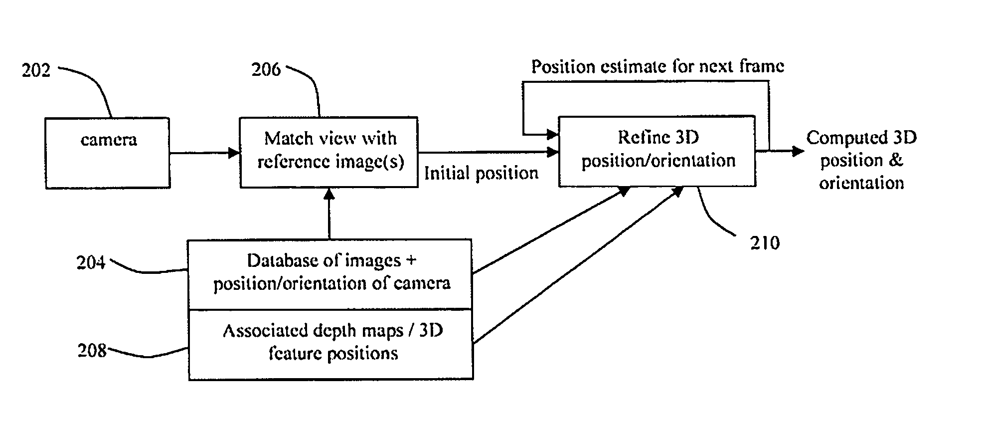
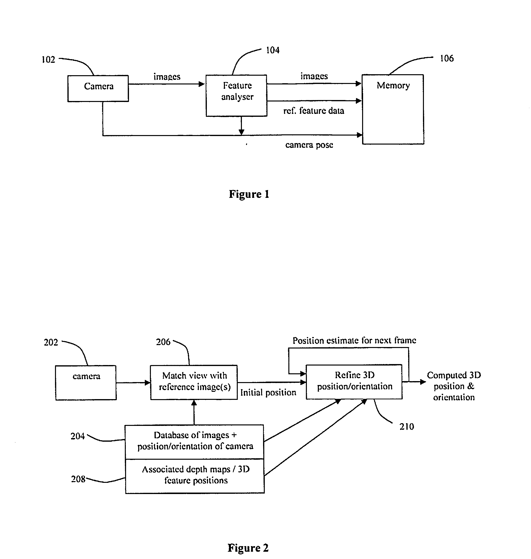
[0014] Creating a 3D model of a scene is a conventional method of estimating the required information. Theoretically it is logical and easy to understand. In practice, however, we have found that the limitations of accuracy with which the model can be created and used in reality, as well as the manual and computational effort, make this problematic for the purpose of virtual production. Rather than create a 3D model of the scene, we propose that a series of reference images of the scene are captured and stored (106 of FIG. 1) before the tracking system is used, covering a range of views that are representative of those that the camera will be expected to see during use. These images could either be captured with a camera (102 of FIG. 1) similar or identical to the camera that is to be tracked, or could be captured with a high-resolution stills camera. Such a camera fitted with a wide-angle lens provides a convenient way of rapidly acquiring a set of images that contain a high level ...


PUM


Abstract

A method for determining the position and orientation of a camera, which may not rely on the use of special markers. A set of reference images may be stored, together with camera pose and feature information for each image. A first estimate of camera position is determined by comparing the current camera image with the set of reference images. A refined estimate can be obtained using features from the current image matched in a subset of similar reference images, and in particular, the 3D positions of those features. A consistent 3D model of all stored feature information need not be provided.

Description

PRIOR APPLICATION DATA [0001] The present application claims priority from prior United Kingdom application number GB 0403051.6 filed Feb. 11, 2004, incorporated herein by reference in its entirety. FIELD OF THE INVENTION [0002] The present invention relates to position determination, particularly but not exclusively for determination of the position of a camera. In preferred aspects, position and orientation, herein referred to as “pose” are determined. BACKGROUND OF THE INVENTION [0003] In applications such as TV production it is often necessary to render virtual objects so that they appear to be a part of a real scene. When the camera capturing the real scene is moving, it is necessary to estimate for each captured frame its pose (pan, tilt, roll, and x, y, z position), as well as its focal length, so that the virtual objects in the scene can be rendered to match. There are normally six degrees of freedom (although camera constraints, e.g. fixed cameras or cameras mounted on a tr...

Claims


Application Information

Patent Timeline
IPC IPC(8): G06T7/00G06V10/147H04N5/222
CPCG06K9/209H04N5/2224G06T2207/30244G06T7/0044G06T7/74G06V10/147G06T7/60H04N5/272
Inventor THOMAS, GRAHAM ALEXANDERCHANDARIA, JIGNAFRASER, HANNAH MARGARETGRAU, OLIVERBRIGHTWELL, PETER JOHN
Owner BRITISH BROADCASTING CORP
Why Eureka
Try Eureka