Gaming machine with payout table

Inactive Publication Date: 2005-09-01
UNIVERSAL ENTERTAINMENT CORP
View PDF43 Cites 119 Cited by
  • Summary
  • Abstract
  • Description
  • Claims
  • Application Information

AI Technical Summary

Benefits of technology

[0007] However, the suchlike gaming machine aims to increase motivation for the player to bet more gaming media, by changing the payout table in accordance with the number of gaming media being bet by the player to realize that the player may have more chances to get the payout. Therefor

Problems solved by technology

Therefore, in a gaming machine which pays out more coins as an award in accordance with coins having been bet by the player, it is not easy to displ

Method used


Image

  • Gaming machine with payout table
  • Gaming machine with payout table
  • Gaming machine with payout table

Examples


Embodiment Construction

[0153] The preferred embodiment of the present invention will be described below in reference to the drawings. However, the present invention is not limited to the embodiment, and various modifications and changes in design can be made without departing from the scope of the present invention.

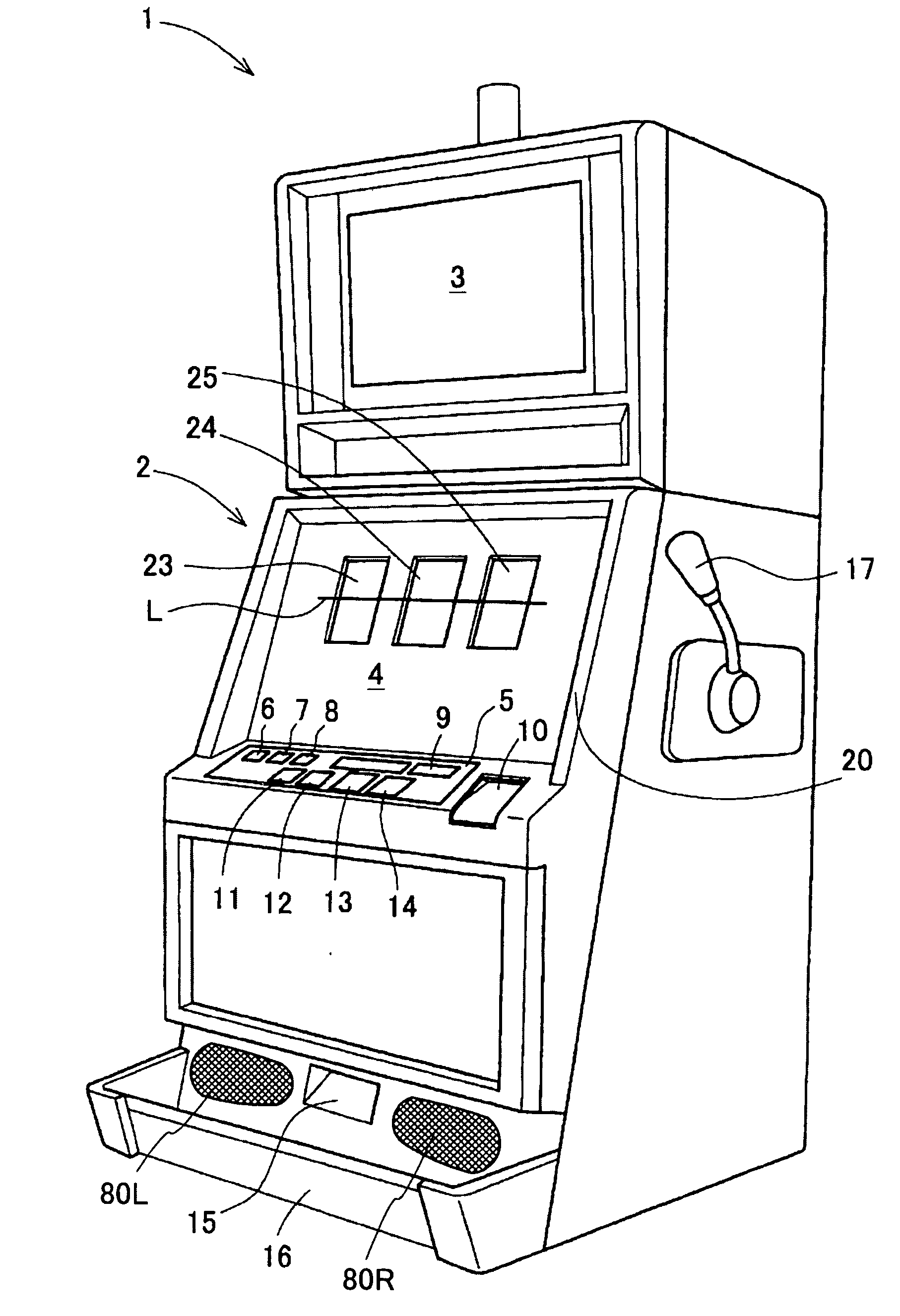
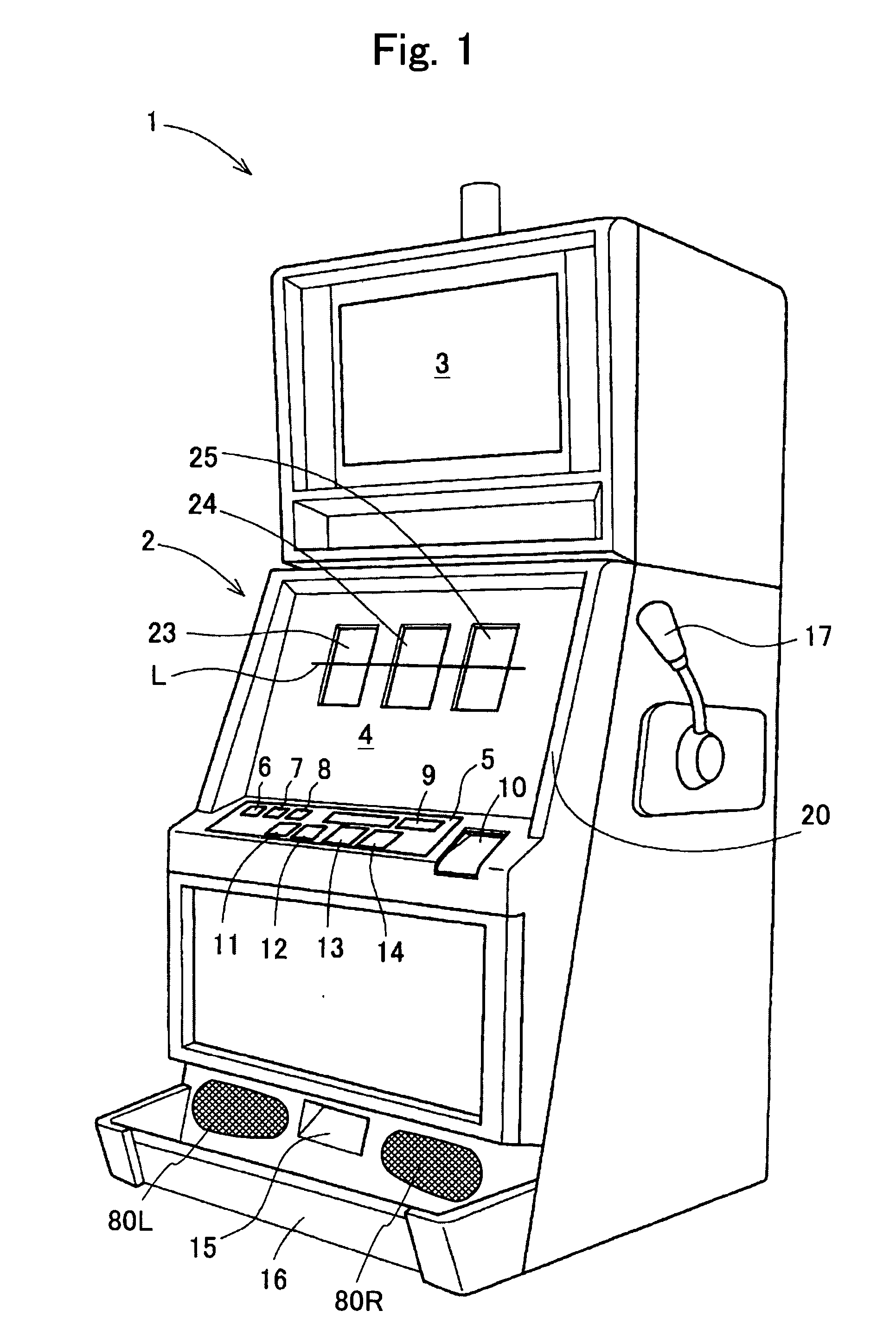
[0154] Hereinafter, a slot machine 1 which relates to this embodiment will be described with reference to drawings. Firstly, an outline configuration of the slot machine 1 which relates to the embodiment will be described on the basis of FIGS. 1 and 5. Meanwhile, in this embodiment, as one example of a slot machine, the slot machine 1 will be described as an example. FIG. 1 is a perspective view of the slot machine 1.

[Exterior Appearance of Slot Machine 1]

[0155] In FIG. 1, the slot machine 1 has a cabinet 2 which forms the entirety thereof, and a sub display 3 is disposed on a front surface upper portion of the cabinet 2, and in addition, a main display 4 is disposed on a front surface cente...


PUM


Abstract

A slot machine comprising a payout display device, which performs a high display effect, is provided. The slot machine 1 is provided with a sub display 3. The sub display 3 displays a payout table showing payout information about payout amount distributed to a player depending on the number of coins bet by the player and the winning combination.

Description

CROSS-REFERENCE TO RELATED APPLICATIONS [0001] This application is based upon and claims the benefits of priority from Japanese Patent Application No. 2004-055541 filed on Feb. 27, 2004, the entire contents of which are incorporated herein by reference. [0002] This application is related to a co-pending U.S. patent application Ser. No. ______ entitled “Gaming Machine With Game Effect” and “Gaming Machine With Reel Window,” and both being filed on even date herewith. The co-pending applications are expressly incorporated herein by reference. FIELD OF THE INVENTION [0003] This invention relates to a gaming machine such as a slot machine which is provided with variable display means such as reels which carries out variable display of symbols necessary for a game, control means such as a microcomputer, and so on. RELATED ART [0004] In the past, as this kind of a gaming machine, there has been, for example, a slot machine. A game on a slot machine is started by inserting a coin into a sl...

Claims


Application Information

Patent Timeline
IPC IPC(8): A63F5/04G07F17/32
CPCG07F17/3211G07F17/3202
Inventor IWAMOTO, HIDEAKI
Owner UNIVERSAL ENTERTAINMENT CORP
Why Eureka
Try Eureka