Polyaxial pedicle screw assembly

a technology of pedicle screw and screw assembly, which is applied in the direction of ligaments, prostheses, osteosynthesis devices, etc., can solve the problems of reducing fatigue resistance, unable to lock into the desired position of conventional polyaxial systems, and reducing fatigue resistance, so as to achieve more lateral range of motion

Inactive Publication Date: 2005-09-01
CUSTOM SPINE INC
View PDF82 Cites 314 Cited by
  • Summary
  • Abstract
  • Description
  • Claims
  • Application Information

AI Technical Summary

Benefits of technology

[0014] The embodiments of the invention provide a polyaxial spinal screw that can become rigid similar to a monoaxial screw inter-operatively on demand. The embodiments of the invention also offer the surgeon more lateral range of motion than conventional products by utilizing the space under the screw head to provide a bigger arc of rotation. Moreover, the saddle pin component offers the flexibility to use a diametrical range of spinal rods instead of a fixed size rod.

Problems solved by technology

Surgical procedures treating spinal injuries are one of the most complex and challenging surgeries for both the patient and the surgeon.
However, due to the complexity of the human anatomy, most surgeons must bend the rod (causing notches thereby reducing fatigue resistance) before placing them into two or more non-aligned pedicle screws in order to properly stabilize the pedicle screw assembly within the patient's body.
For example, during scoliosis surgery conventional polyaxial systems typically cannot lock into a desired position to persuade the spinal column into desired correction before final construct assembly.
Most conventional top loading polyaxial spine screws do not do enough to address cantilever failure of the assembly components.
Additionally, most polyaxial screws generally do not offer enough flexibility because the rod sits too closely on top of the center of rotation.
Furthermore, most top loading screw systems generally do not accommodate different rod sizes.

Method used


Image

  • Polyaxial pedicle screw assembly
  • Polyaxial pedicle screw assembly
  • Polyaxial pedicle screw assembly

Examples


first embodiment

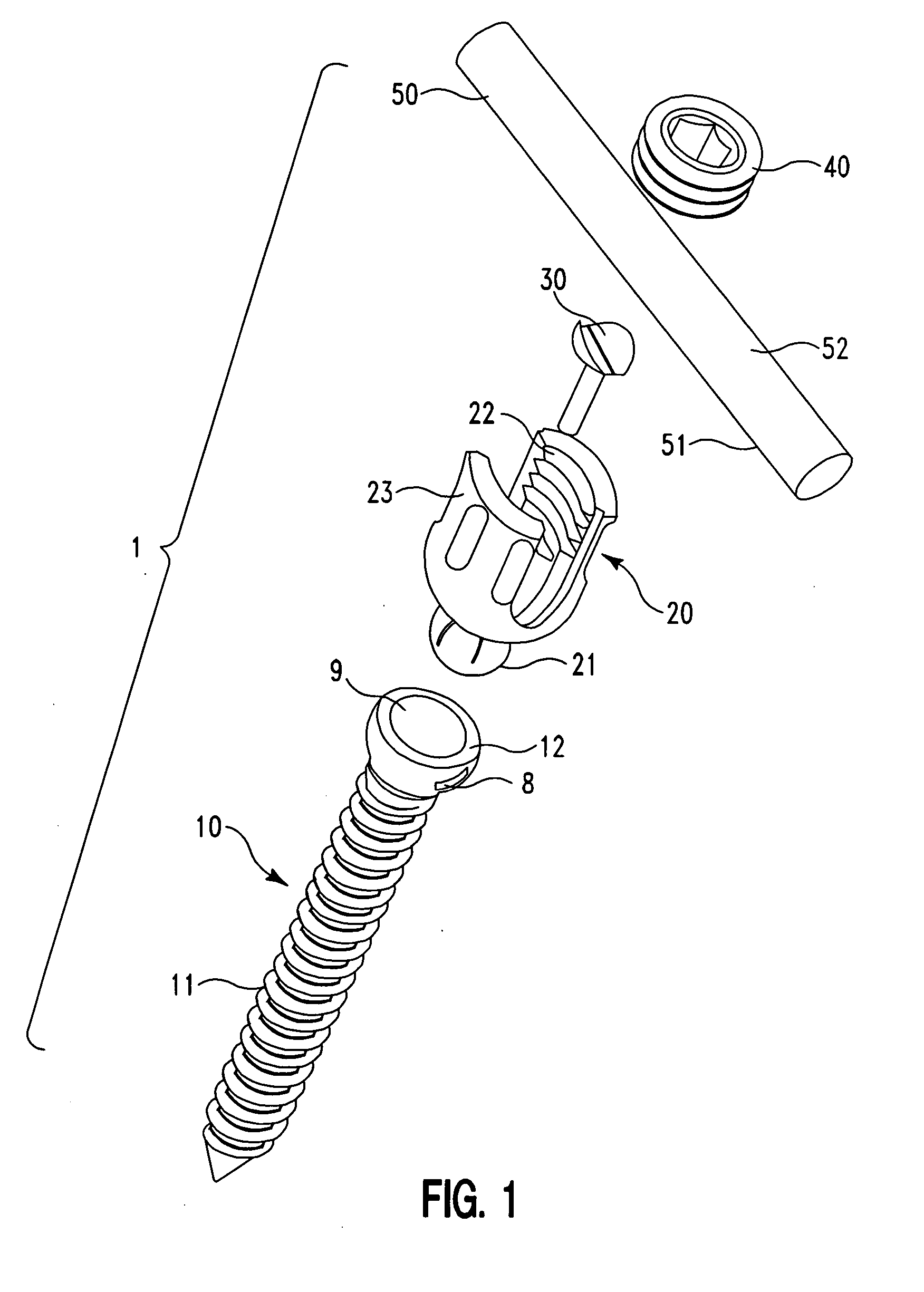
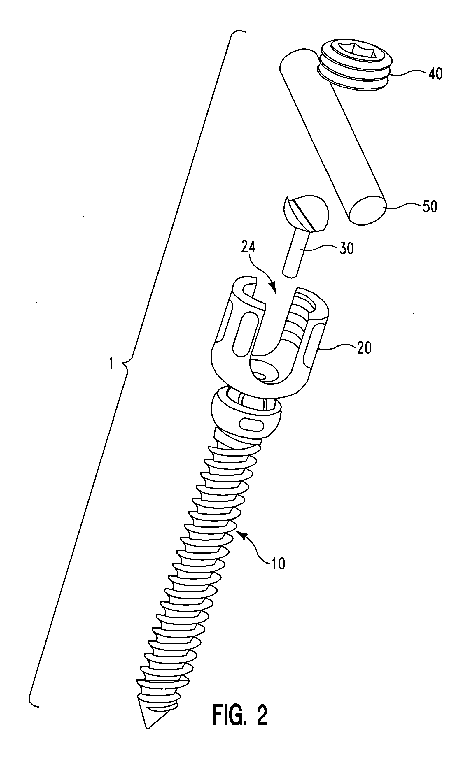
[0035]FIGS. 1 through 6 provide an exploded view of the pedicle screw assembly 1 according to the invention. The screw assembly 1 comprises a bone screw (fixator component) 10 having a threaded end 11 for engaging a bone (not shown) and a concave female socket end 12 for engaging and receiving the screw head 20.

[0036] As implemented, the screw head 20 is first snapped into place in the bone screw 10 as shown in FIG. 2. Then, as shown in FIG. 3 the saddle pin 30 snaps into place in the lower base portion 25 of the screw head 20, which includes a groove 26 (best seen in FIG. 7) for receiving the saddle pin 30. In the manufacturing process, once the saddle pin 30 snaps into place, the screw assembly 1 is prepared for ultra sonic cleaning to remove any impurities and subsequently may be shipped in this manufactured format (with the saddle pin 30 connected to the screw head 20, which is connected to the bone screw 10).

[0037]FIG. 7 shows that the female spherical pocket 12 of the bone sc...

second embodiment

[0042]FIG. 10(A) is a perspective view of a bone fixator assembly according to the invention, wherein the bone fixator component is configured as a hook 60. The hook 60 is further illustrated in FIG. 10(B). The hook 60 includes a concave socket 12 having an inner portion 9 adapted to receive the bulbous end 21 of the screw head 20; and a dimpled outer portion 8. The hook 60 further includes a pair of arms 61, 62 connected by a connection arm 64. A space 63 separates the arms 61, 62 from one another. The arms 61, 62 are configured to receive an additional member (not shown) for subsequent attachment to the bone.

[0043] The several embodiments of the saddle pin 30 are shown in FIGS. 11(A) through 14. The saddle pin 30 provides a proper seat for the longitudinal member 50 and avoids notching a typical titanium longitudinal member 50 (titanium is very notch sensitive). Furthermore, the saddle pin 30 allows one to accommodate multiple sizes of longitudinal members 50 in the same screw ass...


PUM


Abstract

A pedicle fixation assembly and method for assembly comprises a screw head comprising a male bulbous end; a bone fixator component comprising a female concave semi-spherical socket for receiving the screw head; a locking saddle pin for engaging the screw head and the bone fixator component; and a blocker for engaging the screw head and for securing the longitudinal member.

Description

CROSS REFERENCE TO RELATED APPLICATION [0001] This application claims the benefit of U.S. Provisional Patent Application No. 60 / 548,543 filed on Feb. 27, 2004 and U.S. Provisional Patent Application No. 60 / 565,658 filed on Apr. 2, 2004, the contents of which in their entireties are herein incorporated by reference.BACKGROUND OF THE INVENTION [0002] 1. Field of the Invention [0003] The embodiments of the invention generally relate to medical devices and assemblies, and more particularly to an orthopedic surgical implant assembly used in the field of surgical lumbar, thoracic and cervical spine treatment. [0004] 2. Description of the Related Art [0005] Surgical procedures treating spinal injuries are one of the most complex and challenging surgeries for both the patient and the surgeon. When there are various deformities, trauma, or fractures of the vertebra, surgeons may attempt to “fuse” them together by attaching screw-like devices into the pedicles of the spine and thereby connect...

Claims


Application Information

Patent Timeline
Patent Type & Authority Applications(United States)
IPC IPC(8): A61B17/70A61F2/30
CPCA61B17/7037A61B17/7032
Inventor ABDELGANY, MAHMOUD F.
Owner CUSTOM SPINE INC
Why Eureka
Try Eureka