Modular storage system

Active Publication Date: 2005-09-08
STEELCASE INC
View PDF81 Cites 10 Cited by
  • Summary
  • Abstract
  • Description
  • Claims
  • Application Information

AI Technical Summary

Benefits of technology

[0011] In another aspect of the present invention, a cabinet assembly for storing office materials and personal effects includes a cabinet having panels defining a cabinet storage space and front edges defining a first access opening to the cabinet storage space. A cabinet shelf is located entirely within the cabinet storage space. A storage door is pivoted to the cabinet and shaped to selectively close the access opening. The storage door includes side sections defining a door storage space and defining a second access opening to the door storage space. The door includes shelves defining storage compartments within the door storage space sufficient in size and shape to hold office articles and personal articles having thickness and weight. The door has a castor adapted to support a free edge of the door on a floor surface to prevent forward tipping of the cabinet when the door is in an open position and when the storage compartments are loaded. The door storage space is additive to the cabinet storage space when the door is closed and characteristically does not intrude into the cabinet storage space. By this arrangement, when the door is in the open position, the cabinet storage space and door storage space can be individually and easily accessed without having to reach into the other of the cabinet storage space and door storage space, and further a rear of the cabinet storage space and door storage space can be individually reached without having to reach a distance equal to a total depth of the cabinet and door storage spaces.

Problems solved by technology

In-process inventory is expensive to keep on-hand and to keep track of.
Further, it adds complexity to the manufacturing process and often adds to manual labor.
Further, alignment of edges on adjacent panels can be a problem.

Method used


Image

  • Modular storage system
  • Modular storage system
  • Modular storage system

Examples


Embodiment Construction

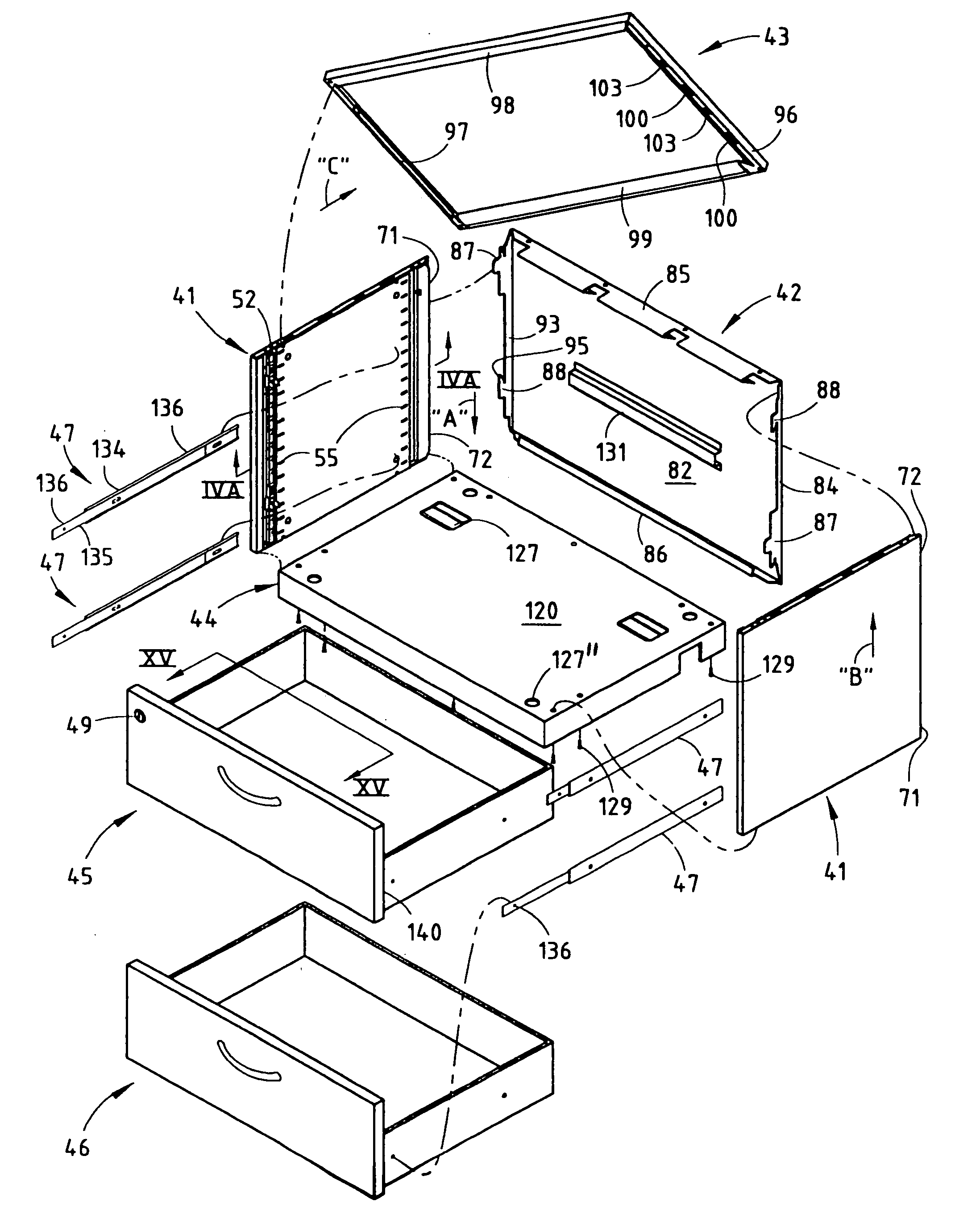
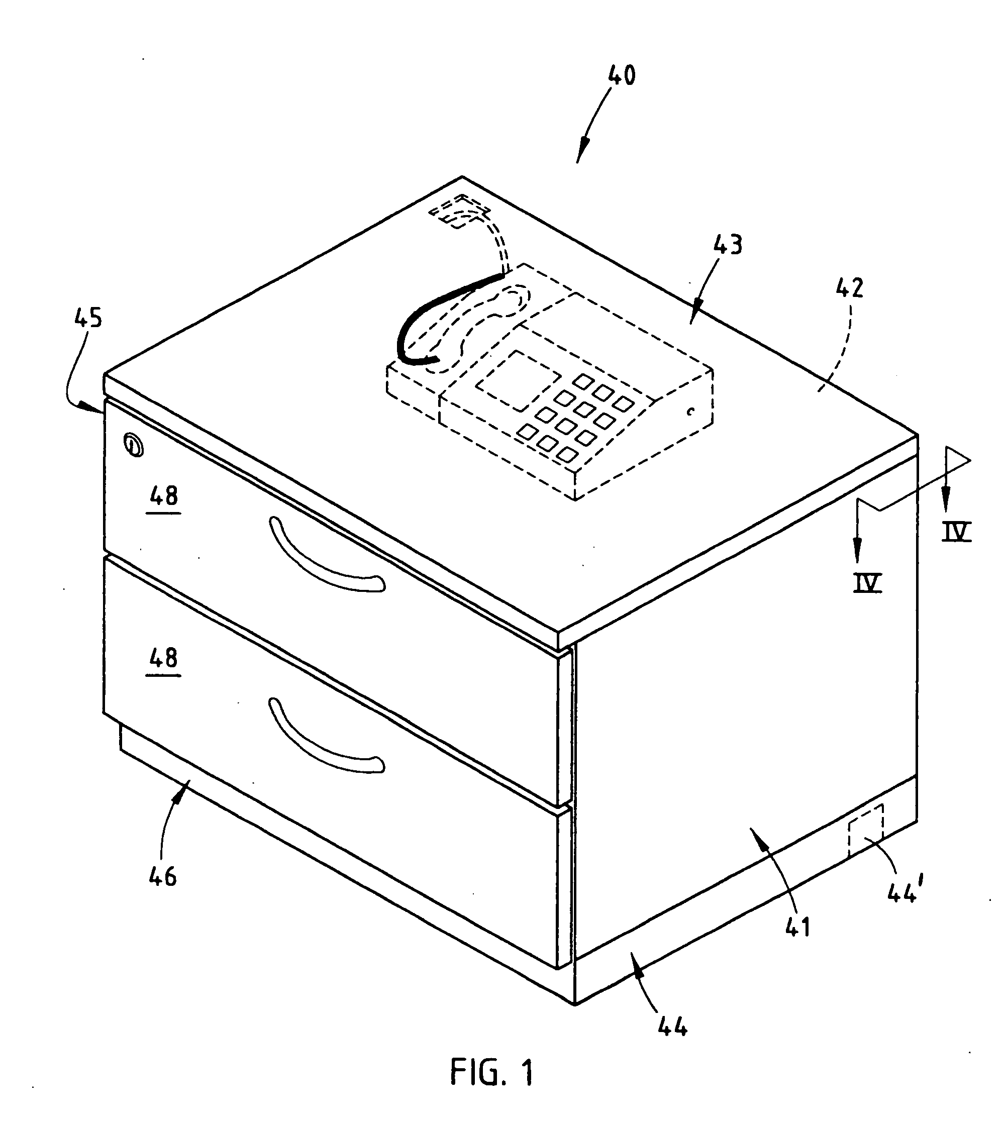
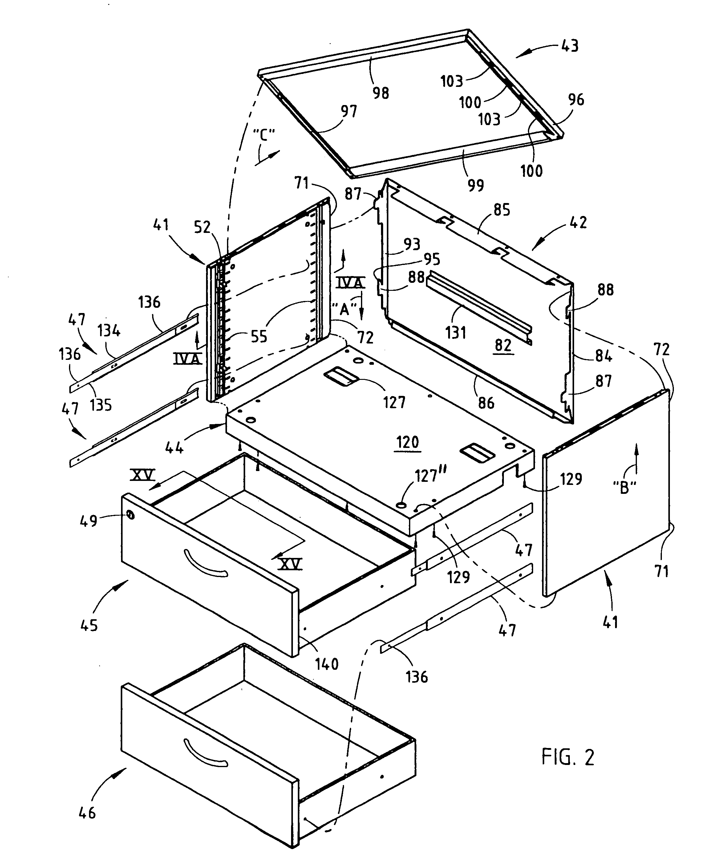
[0048] A cabinet 40 (FIGS. 1-2) includes side panels 41, a back panel 42 and a top panel 43 that frictionally attach together with non-intrusive integrally formed connecting flanges and without separate fasteners. The illustrated base or bottom panel 44 is screw-attached, and includes openings 44′ for routing wiring within the cabinet 40. Two drawers 45 and 46 are supported on drawer glides 47, respectively (FIG. 2). The drawer 45 includes a hollow header 48 which carries a lock 49, a cam 50 (FIG. 14) operably connected to the rear of the lock 49, and a bent horizontal lock rod 51 adapted to operably engage a vertical locking bar 52 (FIGS. 2, 12A and 14) in response to turning of the lock 49 and cam 50, as discussed below. Shelf brackets 53 (FIG. 18) are adapted to support shelves 54 in the cabinet 40B in either a flush condition or an inset condition (FIG. 18), and at different heights (FIG. 19) based on which cabinet slots 55 they engage and based on their orientation in those slo...


PUM


Abstract

A cabinet includes side panels, a back panel, and a top panel that frictionally-attach together with non-intrusive integrally-formed connectors. The illustrated base is screw-attached, and includes openings for routing wiring within the cabinet. Brackets are adapted to support shelves in the cabinet in either a flush or inset condition, and at different heights based on which cabinet slots they engage and based on their orientation in those slots. A light-transmitting top panel and top shelf can be used to provide improved light within the cabinet. Hinge brackets on the cabinet support either a thick door with internal storage space, a proud door or an inset door. Drawers supported in the cabinet include a lock within the drawer's header for operating a vertical cabinet lock rod.

Description

CROSS-REFERENCE TO RELATED APPLICATION [0001] This application is a divisional of U.S. patent application Ser. No. 10 / 095,980, filed Mar. 12, 2002, entitled MODULAR STORAGE SYSTEM, the entire disclosure of which is incorporated herein by reference.BACKGROUND [0002] The present invention relates to modular storage units, such as cabinets with drawers and / or shelves, and more particularly relates to a modular storage unit having top, side, and back panels that frictionally attach with the use of integrally-formed interfitting flanges that are secure but non-intrusive and releasable. Several concepts are integrated into the storage units to improve the ability to assemble the units, to provide rearrangeability of shelves without the need for separate shelf brackets, to reduce cost, and to reduce the number of components, all without reducing the ability to provide a customized cabinet adapted to meet specialized needs. [0003] In-process inventory is expensive to keep on-hand and to kee...

Claims


Application Information

Patent Timeline
IPC IPC(8): A47B47/02A47B57/40A47B67/04A47B87/02E05B65/46E05B65/462
CPCA47B47/02A47B57/404E05B65/462A47B87/0284A47B67/04
Inventor YOUNGS, BRADLEY D.NELSEN, RANDALL P.WIERSMA, TIMOTHY J.LONGHURST, KEVIN J.BUFFINGA, KEITH L.KORRECK, WILLIAM A.JOURDEN, MICHAEL A.EILMUS, NIELS JOACHIMWELSH, MICHAEL W.
Owner STEELCASE INC
Why Eureka
Try Eureka