Base lock television stand

Inactive Publication Date: 2009-08-06
PINNACLE DESIGN
View PDF103 Cites 2 Cited by
  • Summary
  • Abstract
  • Description
  • Claims
  • Application Information

AI Technical Summary

Benefits of technology

[0014]In an exemplary embodiment, the system stand includes a support surface, a first retaining element, and a second retaining element. The stand is configured to support the display device on the support surface. The first and second retaining elements are received by the stand, e.g., in a recess, over the support surface and positioned over one end of the support portion, e.g., a lower end resting on the support surface. The stand prevents vertical motion of the first and second retaining elements relative to the support surface. The one end of the support portion is seated in a chamber defined at least by the support surface and the first and second retaining elements. The first and second retaining elements have edges which contact along a first length, are spaced apart along a second length, and contact along a third length. The display device support portion passes through an opening defined by the edges along their second lengths. At least one of the chamber and the opening is sized so as to prevent tipping of the display device relative to the stand support surface.
[0017]A system according to another exemplary embodiment of the present invention includes a stand and a display device, which is one of a flat panel television and a flat panel monitor. The system stand includes two or more legs, a fixed top portion connected to the two or more legs, a removable top portion, and a retaining element. The fixed top portion includes a pair of opposing recesses along an internal surface of the fixed top portion. A horizontal support surface is connected to the fixed top portion and supports the system display device. The retaining element is slidingly received within the recesses over the support surface. A top surface of each of the fixed top portion, the removable top portion, and the retaining element together form a top surface of the stand. The support surface, the retaining element, the internal surface of the fixed top portion, and an internal surface of the removable top portion define a chamber containing a first portion of the support portion of the display device, e.g., the lower end of the support portion resting on the support surface. A second portion of the support portion, e.g., between the first portion and the display, extends out of the chamber through a hole. The hole is defined by a cut-out in the retaining element and a portion of the internal surface of the fixed top portion facing the cut-out. The hole may be sized relative to the second portion of the support portion so as to prevent tipping of the display device relative to the support surface. The chamber may sized relative to the first portion of the support portion so as to prevent tipping of the display device.
[0018]A method according to an exemplary embodiment of the present invention for supporting a display device, the display device comprising a display portion and a support portion connected to the display portion, the support portion configured to support the display portion in an upright vertical position when placed on a generally flat horizontal surface, includes the steps of: (a) positioning a first retaining element over and adjacent a support surface and fixing the retaining element in a vertical direction relative to the support surface; (b) placing the support portion on the support surface adjacent the first retaining element; and (c) positioning a second retaining element over and adjacent the support surface opposite the first retaining element and constraining vertical motion of the second retaining element relative to the support surface. The first and second retaining elements preventing tipping of the display device relative to the support surface. At least one end of the support portion positioned directly between the support surface and the first and second retaining elements and concealed from view by the support surface and the first and second retaining elements.
[0025]Another exemplary method for supporting a display device on a display device stand according to the present invention, includes the steps of: (a) placing the support portion on a support surface of the display device stand, the body including a fixed top portion; and (b) positioning a removable top portion (i) over and adjacent the support surface, (ii) opposite the fixed top portion, and (iii) at least partially over the support portion, and constraining vertical motion of the removable top portion relative to the support surface. The fixed and removable top portions lying in the same plane form at least a portion of the top surface of the stand. At least one end of the support portion is positioned directly between the support surface and the fixed and removable top portions and is at least partially concealed from view by the fixed and removable top portions. The fixed and removable top portions prevent tipping of the display device relative to the support surface.

Problems solved by technology

Given the typical weight distribution and dimensions of a flat panel display, i.e., very narrow (having very little depth) compared to its height and width, flat panel displays seated on such generic stands may tip if improperly handled.

Method used


Image

  • Base lock television stand
  • Base lock television stand
  • Base lock television stand

Examples


Embodiment Construction

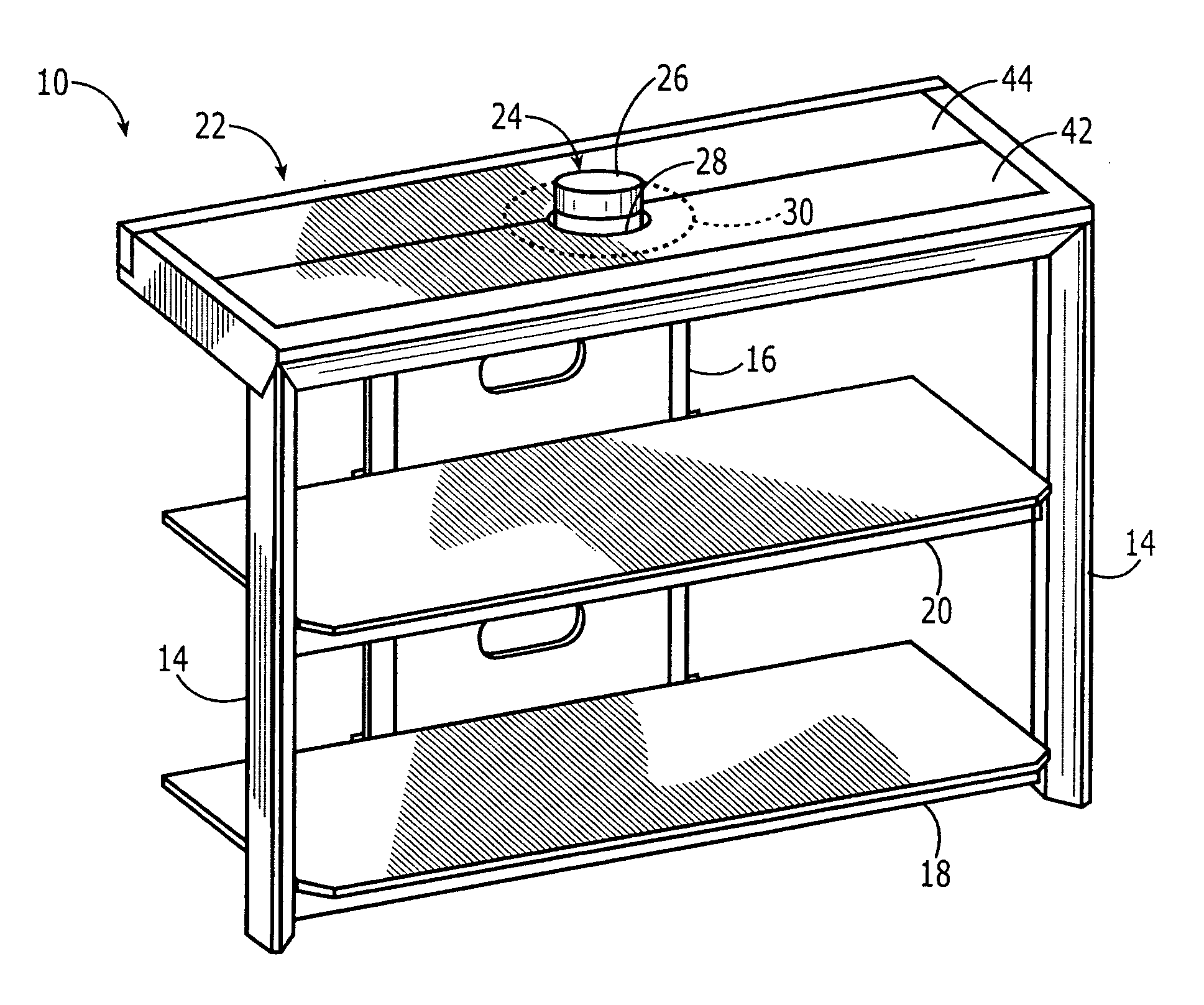
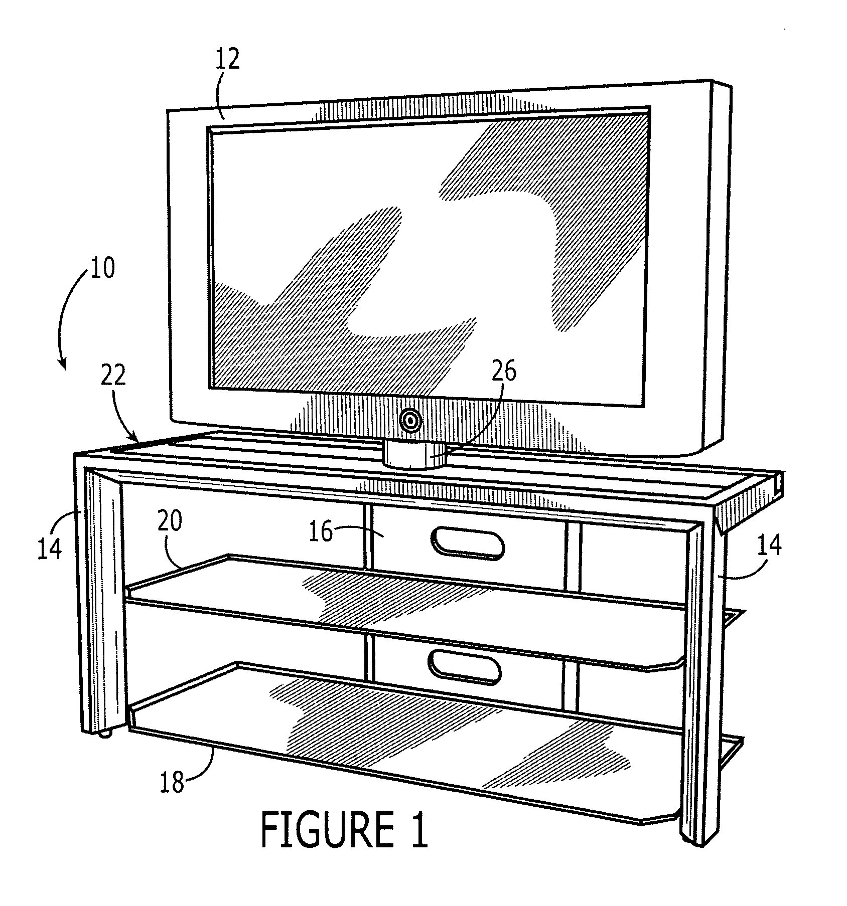
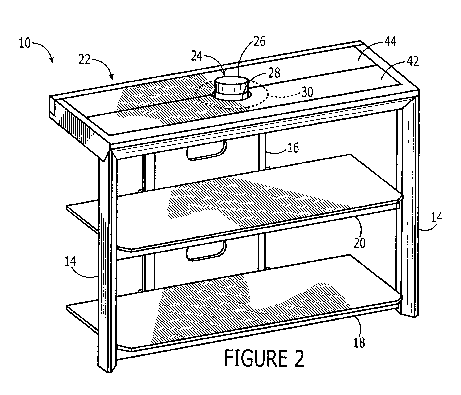
[0037]FIG. 1 illustrates a stand 10 for a display device 12 including two front legs 14, a back leg 16, a lower shelf 18, an upper shelf 20, and a top 22. Display device 12 is connected to and rests on a support element 24, which is partially concealed by top 22.

[0038]Display device 12, as shown in FIG. 1, is a flat panel television or monitor, such as a LCD or plasma flat panel television, but may be any display device similar in configuration, i.e., having a narrow depth, relative to its height and width, and / or a weight distribution rendering it prone to tipping when supported from beneath.

[0039]Further, the arrangement and use of legs and shelves is merely exemplary. Top 22 may be supported in any number of different ways. For example, top 22 may be secured to the top surface of an appropriately sized chest, pedestal, desk, or other furniture, thereby obviating the need for legs 14, 16 and / or shelves 18, 20 all together. Top 22 may also be supported from above, e.g., by cables h...


PUM


Abstract

A base lock stand for a flat panel display, e.g., a LCD or plasma television or monitor, including a top surface configured to prevent tipping of the display and / or to conceal a portion of the display support. In an exemplary embodiment, the top surface is slidingly received in a stand recess over a bottom portion of the display support.

Description

FIELD OF THE INVENTION[0001]The present invention relates to furniture. More particularly, the present invention relates to a stand for a flat panel display, e.g., a flat panel television or monitor.BACKGROUND INFORMATION[0002]Generic television stands exist that have been used to support flat panel displays, such as LCD and plasma televisions and monitors. The displays may be connected to a support element, which is generally seated on a top surface of the stand. Given the typical weight distribution and dimensions of a flat panel display, i.e., very narrow (having very little depth) compared to its height and width, flat panel displays seated on such generic stands may tip if improperly handled. Therefore, there exists a need for a stand configured to support and prevent tipping of a flat panel display.SUMMARY OF THE INVENTION[0003]Reference throughout this document to “one embodiment” or “an embodiment” or “an exemplary embodiment.” etc., means that a particular feature, structur...

Claims


Application Information

Patent Timeline
IPC IPC(8): F16M11/02F16M13/00F16M11/20
CPCA47B2200/04A47B81/06
Inventor FRIDLEY, TODDCOX, JUSTIN A.
Owner PINNACLE DESIGN
Why Eureka
Try Eureka