Riding lawnmower outrigger

Inactive Publication Date: 2008-12-25
SUTTON CHARLES E
View PDF10 Cites 10 Cited by
  • Summary
  • Abstract
  • Description
  • Claims
  • Application Information

AI Technical Summary

Benefits of technology

[0006]The primary object of the present invention is to provide a riding lawnmower outrigger that prevents tipping of a riding lawnmower when used on sloped ground surfaces.
[0007]A further object of the present invention is to provide a riding lawnmower outrigger that may be permanently or removably secured to a riding lawnmower.
[0008]An even further object of the present invention is to provide a riding lawnmower outrigger that is easy to use.
[0013]To use the present invention, a user first secures the outer tube to a riding lawnmower, preferably under the riding lawnmower base. Then, he or she adjusts the length of the inner tube to a desired position and locks the inner tube within the inner tube, preferably via a pin and apertures located in the inner and outer tubes. Thus, when the user is using the riding lawnmower on a ground surface having a slope, the riding lawnmower will not tip-over or rollover because the riding lawnmower outrigger acts as a supporting arm to balance the riding lawnmower and prevent tip-over thereof.

Problems solved by technology

However, there is a great risk associated with riding lawnmowers that is not associated traditional push lawnmowers.
Because a user sits atop a riding lawnmower, the effects of the riding lawnmower tipping over may be catastrophic as the user may obtain serious bodily injury, such as gashes and broken bones, or even die.

Method used


Image

  • Riding lawnmower outrigger
  • Riding lawnmower outrigger
  • Riding lawnmower outrigger

Examples


Embodiment Construction

[0023]For purposes of describing the preferred embodiment, the terminology used in reference to the numbered components in the drawings is as follows:

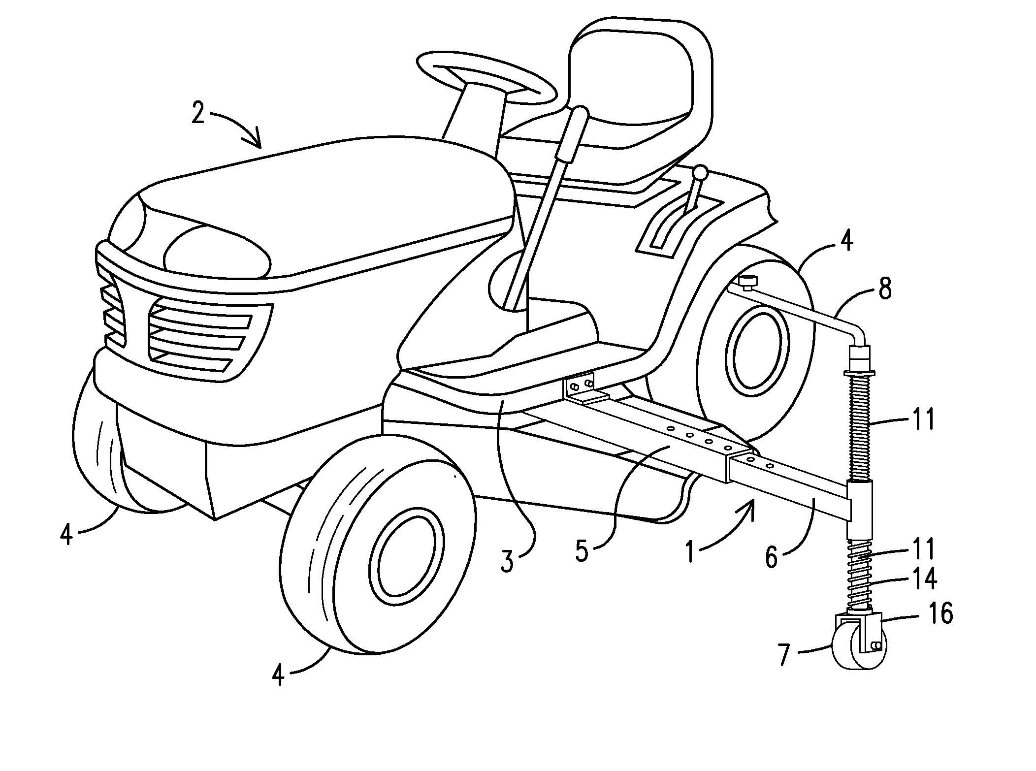
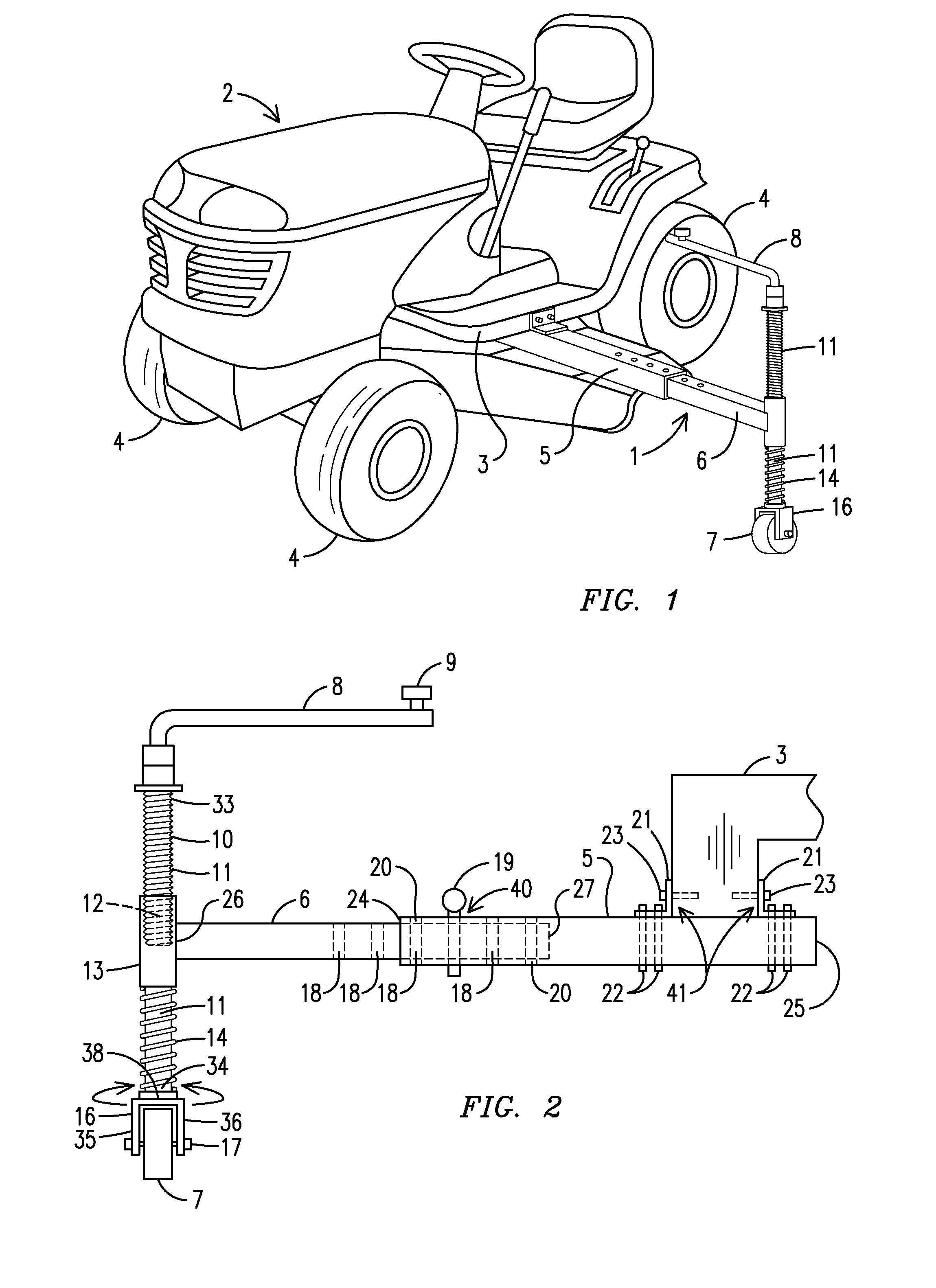
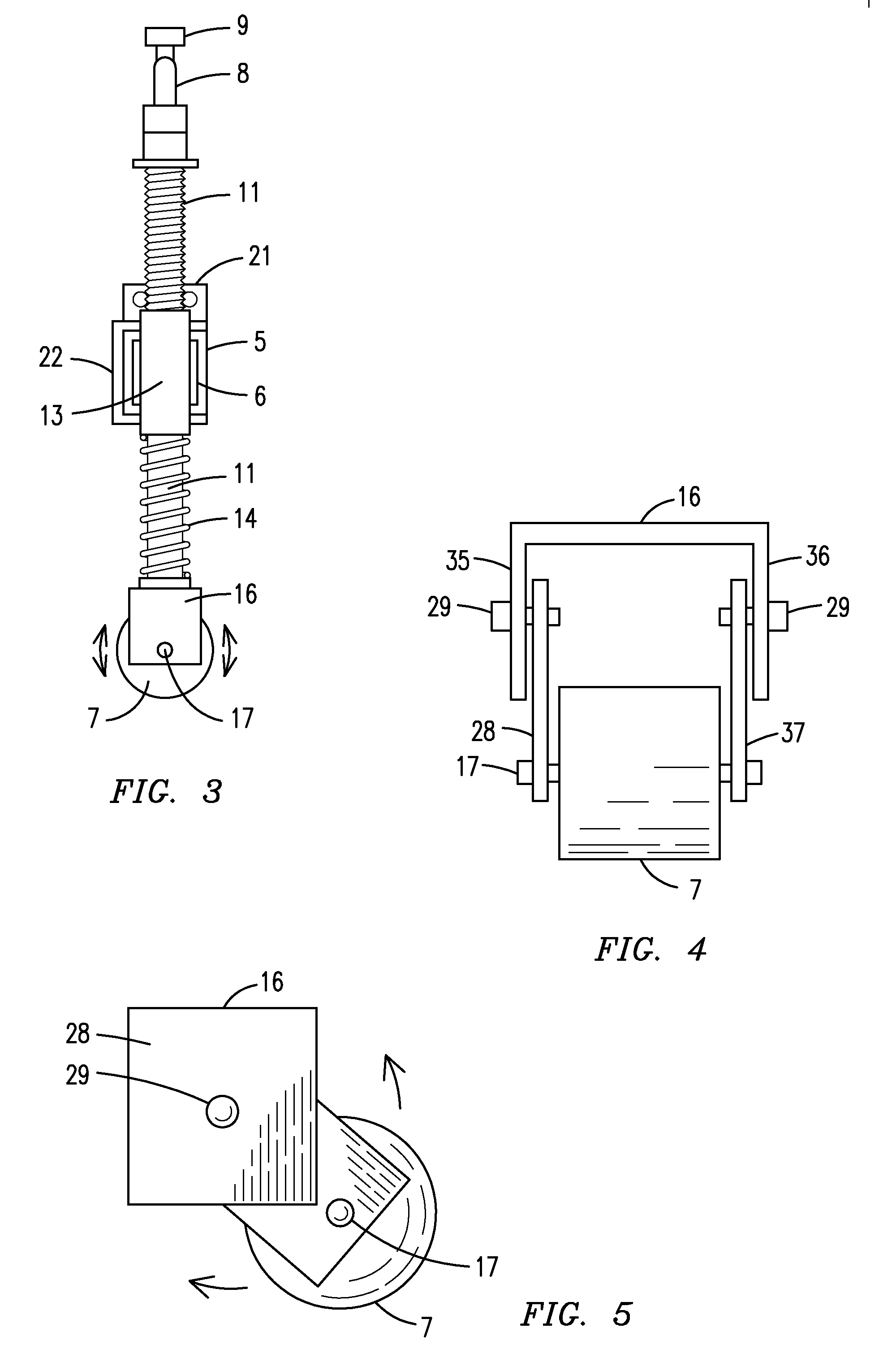
1.riding lawnmower outrigger, generally2.riding lawnmower3.riding lawnmower base4.riding lawnmower tire5.outer tube6.inner tube7.outrigger wheel8.handle9.knob10.vertical tube threads11.vertical tube12.connection tube threads13.connection tube14.spring15.vertical tube aperture16.outrigger wheel housing17.wheel fastening means18.inner tube aperture19.pin20.outer tube aperture21.bracket22.clamp23.bolt24.outer tube first end25.outer tube second end26.inner tube first end27.inner tube second end28.first plate29.pivotal retaining means30.vertical tube plate31.slope32.ground surface33.top end34.bottom end35.outrigger wheel housing first side36.outrigger wheel housing second side37.second plate38.outrigger wheel housing top side39.vertical tube plate aperture40.locking means41.securing means

[0024]With reference to FIG. 1, a side perspective vi...


PUM


Abstract

A riding lawnmower outrigger (1) having a hollow outer tube (5) secured to a riding lawnmower (2), a telescoping inner tube (6) which locks within the outer tube (5), a vertical tube (11) connected to the inner tube (6), an outrigger wheel housing (16) secured to the vertical tube (11) and a wheel (7) secured within the outrigger wheel housing (16). When utilizing the riding lawnmower outrigger (1) on a ground surface (32) having a slope (31), the riding lawnmower (2) will not tip-over or rollover because the riding lawnmower outrigger (1) acts as a supporting arm to balance the riding lawnmower (2) and prevent tip-over thereof.

Description

BACKGROUND OF THE INVENTION[0001]This invention relates to an accessory for a riding lawnmower, more particularly, a riding lawnmower outrigger that may be permanently or removably secured to a riding lawnmower to prevent tipping of the riding lawnmower when used on sloped surfaces.[0002]Riding lawnmowers have become a popular tool for both residential and commercial purposes as the use of riding lawnmowers has many advantages over the use of traditional push lawnmowers. First and most importantly, the amount of energy expended by a person is drastically reduced when comparing the use of a riding lawnmower to a traditional push mower. Second, the amount of time expended by the person to cut a predetermined amount of grass is greatly reduced, thereby permitting a person to cut a larger amount of grass in a shorter amount of time as compared to traditional push lawnmowers. Finally, most people find riding lawnmowers much easier to use than traditional push lawnmowers.[0003]However, th...

Claims


Application Information

Patent Timeline
IPC IPC(8): B62D49/08
CPCB62D49/0671B62D49/08
Inventor SUTTON, CHARLES E.
Owner SUTTON CHARLES E
Why Eureka
Try Eureka