Wheelchair restraint system for a transportation vehicle

Inactive Publication Date: 2005-11-22
AMERICAN SEATING
View PDF59 Cites 18 Cited by
  • Summary
  • Abstract
  • Description
  • Claims
  • Application Information

AI Technical Summary

Benefits of technology

[0012]Advantageously, the front wheel attachment assembly comprising a first front attachment belt for attachment to a first front location of the wheelchair, a second front attachment belt for attachment to a second front location of the wheelchair spaced from the first front location. A first and a second retractor mechanism is provided for retracting the respective first and second belts in a direction to place a tensioning force on the first and second front belts, and the retractor mechanisms include a manual crank for tightening the tensioned first and second belts. The first and second rear attachment belts diverge outwardly from the respective first and second wheelchair locations toward the anchor locations on the bulkhead to effectively prevent lateral tipping. Preferably, the first and second front attachment belts are also inclined downward from the wheelchair to the front bulkhead. The attachment belts diverge outwardly at an angle in a range of about 0 to 15 degrees with respect to the vehicle longitudinal axis, the preferred value being an angle of about 5 degrees with respect to the vehicle longitudinal axis for a standard wheelchair having a 20″ wheel spacing.

Problems solved by technology

However, the problem arises that implementation of these systems is often laborious and time consuming.
Often, the belts are left out and form a hazard for tripping over.
Typically the anchor slots and floor wells used to anchor the belt also present trip and fall hazards.

Method used


Image

  • Wheelchair restraint system for a transportation vehicle
  • Wheelchair restraint system for a transportation vehicle
  • Wheelchair restraint system for a transportation vehicle

Examples


Embodiment Construction

[0025]Referring now to the drawings, the invention will be described in more detail.

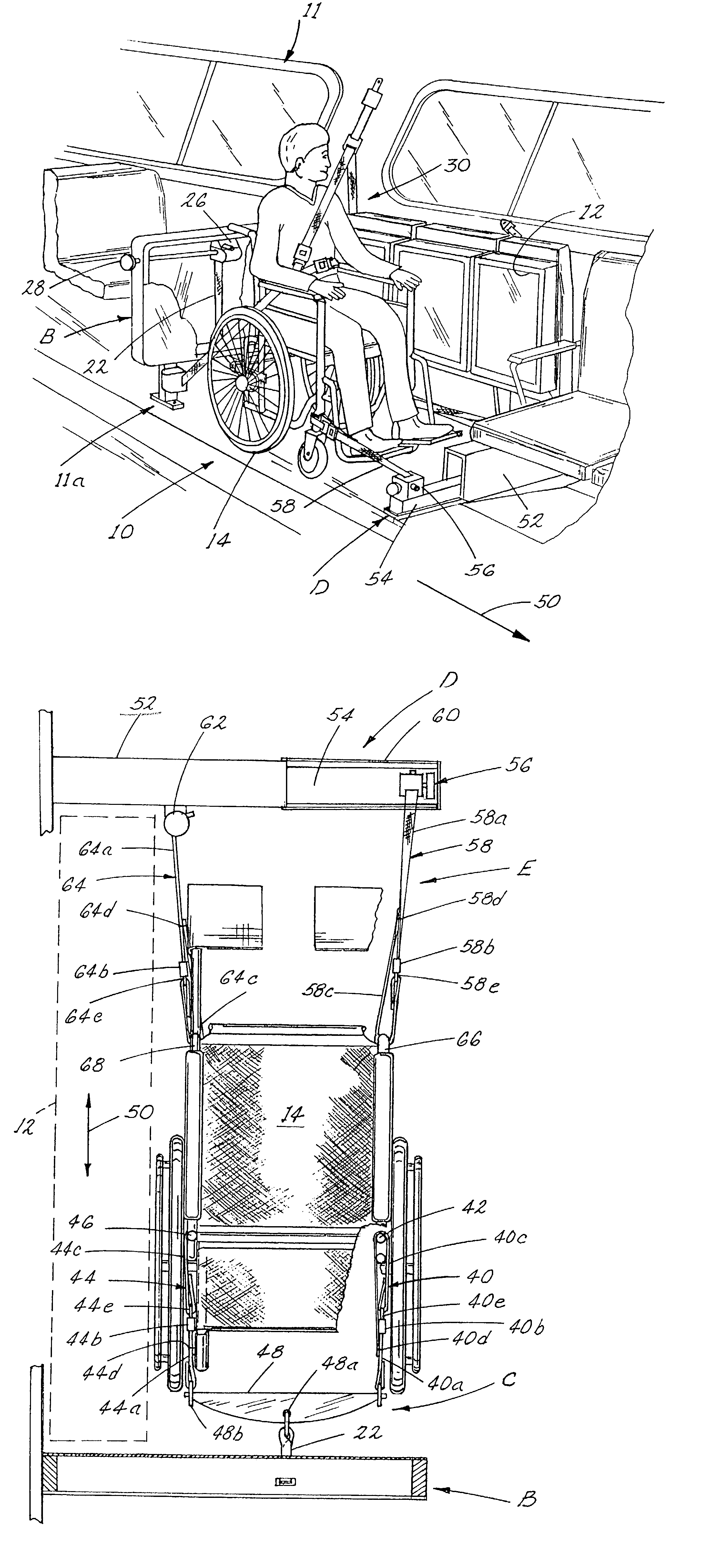
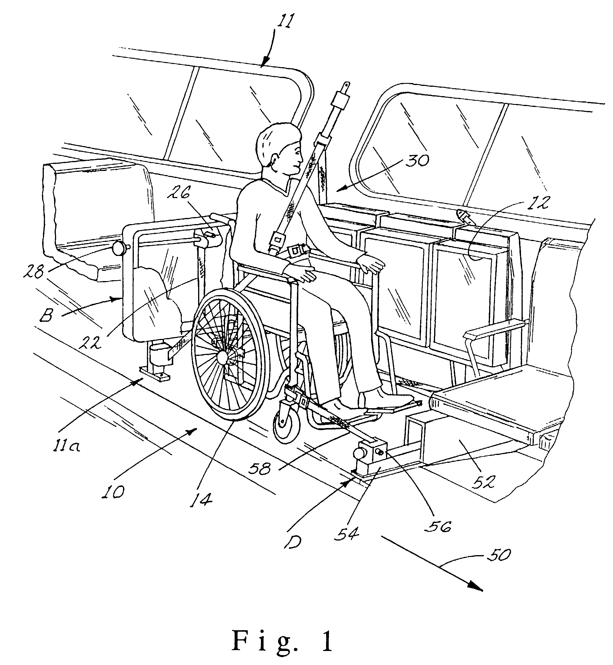
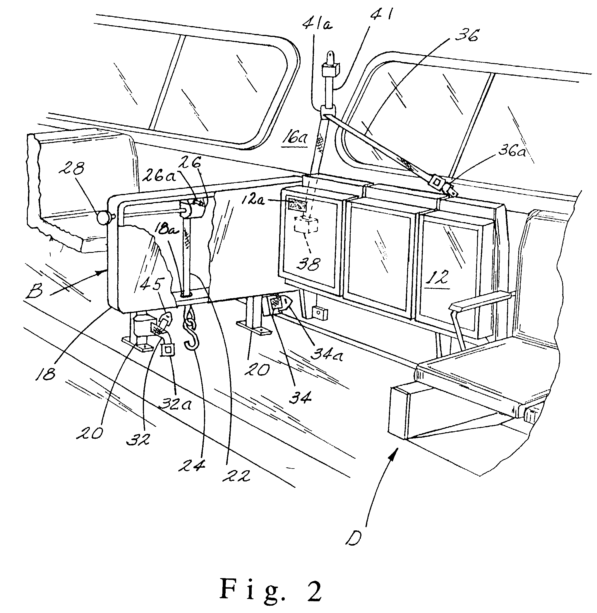
[0026]As can best be seen in FIG. 1, a securement area of a mass transportation vehicle is illustrated, generally at 10, which includes an area for seating of regular passengers or a wheelchair passenger. For this purpose, at least one flip seat 12 is provided which may be positioned between a horizontal seating and a flipped position as shown in FIG. 2. A wheelchair 14 may be secured in the securement area with seat 12 in the flipped position as can best be seen in FIG. 1. The securement area includes a rear barrier, designated generally as B, which includes a housing 18 supported on legs 20 bolted to the floor 11a of vehicle 11. A retractable belt 22 is housed within the barrier housing 18 and extends through a slot 18a terminating in an end to which a hook 24 is secured. A belt / crank retracting mechanism 26 applies a retracting force to belt 22 and a manual crank 28 is provided for tightening a re...


PUM


Abstract

A wheelchair restraint system for a mass transportation vehicle having a securement area for a wheelchair is disclosed which includes a barrier carried at a rear portion of the securement area disposed generally transverse to the longitudinal vehicle axis. A rear wheelchair attachment assembly is carried by the rear barrier for anchoring the wheelchair to the barrier. A personal securement belt assembly secures a seated wheelchair occupant to the wheelchair in the securement area. A front bulkhead extends generally transverse to the longitudinal vehicle axis at a front portion of the securement area which includes an extendable anchor member which extends transverse relative to the longitudinal vehicle axis. The anchor member is extendable between a stored position in which the anchor member is stowed within the bulkhead and a deployed position wherein the anchor member is extended from the bulkhead. A front wheel chair attachment assembly includes two attachment belts extending from the wheel chair to a first anchor location on the bulkhead and to a second anchor location on the extendable anchor member when the anchor member is in the deployed position. The first and second front attachment belts diverge outwardly and incline downwardly from the wheelchair toward the respective first and second anchor locations on the bulkhead to effectively anchor the occupant and wheelchair and prevent lateral tipping.

Description

[0001]This application is a continuation of divisional application Ser. No. 10 / 115,464 entitled Wheelchair Restraint System For A Transportation Vehicle filed on Apr. 3, 2002 now U.S. Pat. No. 6,575,677; which is a continuation of application Ser. No. 09 / 742,634 entitled Wheelchair Restrain System For A Transportation Vehicle filed on Dec. 21, 2000, now U.S. Pat. No. 6,428,254 B2; which is a continuation of application Ser. No. 09 / 390,569 entitled Wheelchair Retrain System For A Transportation Vehicle filed on Sep. 3, 1999, now abandoned; which is a continuation of application Ser. No. 08 / 939,155 entitled Wheelchair Restrain System For A Transportation Vehicle filed on Sep. 29, 1997; now U.S. Pat. No. 6,113,325.BACKGROUND OF THE INVENTION[0002]This invention relates to a wheelchair restraint system for securing a wheelchair and occupant in a mass transportation vehicle such as a bus, train, and the like, and more particularly to a three-point wheelchair restraint system in which the...

Claims


Application Information

Patent Timeline
IPC IPC(8): A61G3/00A61G3/08
CPCA61G3/0808
Inventor CRAFT, RICHARD D.
Owner AMERICAN SEATING
Why Eureka
Try Eureka