Slider for sealable storage bag and sealable storage bag provided with the slider

a sliding device and slider technology, applied in the field of sliding devices, can solve the problems of difficult for users to attach the slider by hand, difficult to push open the front closing portion, and serious defects

Inactive Publication Date: 2005-09-08
ARU
View PDF6 Cites 14 Cited by
  • Summary
  • Abstract
  • Description
  • Claims
  • Application Information

AI Technical Summary

Benefits of technology

[0011] It is a second object of the invention to provide a slider that can completely seal a sealable storage bag and a sealable storage bag provided with the slider.

Problems solved by technology

However, with respect to this conventional slider, it has been difficult to push open the front closing portion 102a counter to the elastic force of the opposing pieces 102 without borrowing the force of an opener.
Thus, with respect to domestic users of the sealable storage bag, it has been difficult for them to attach the slider by hand when the slider has come free from the sealable storage bag.
This becomes a serious defect when the sealable storage bag is used as a compressed bag whose volume is reduced by removing the air inside the bag.

Method used


Image

  • Slider for sealable storage bag and sealable storage bag provided with the slider
  • Slider for sealable storage bag and sealable storage bag provided with the slider
  • Slider for sealable storage bag and sealable storage bag provided with the slider

Examples


Embodiment Construction

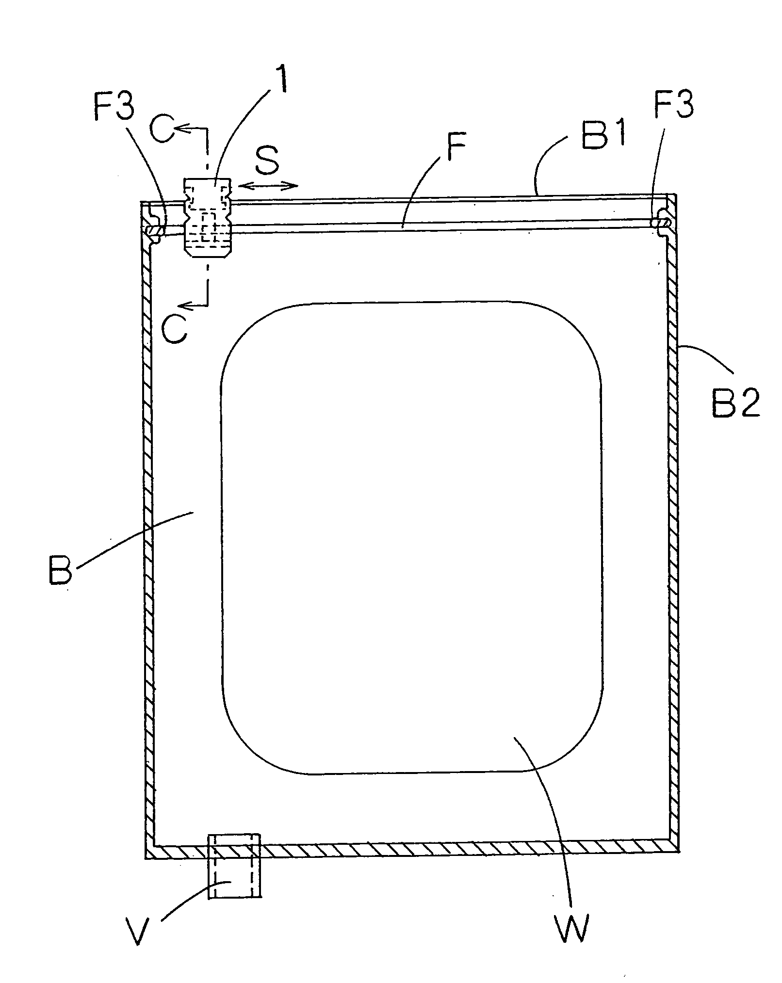
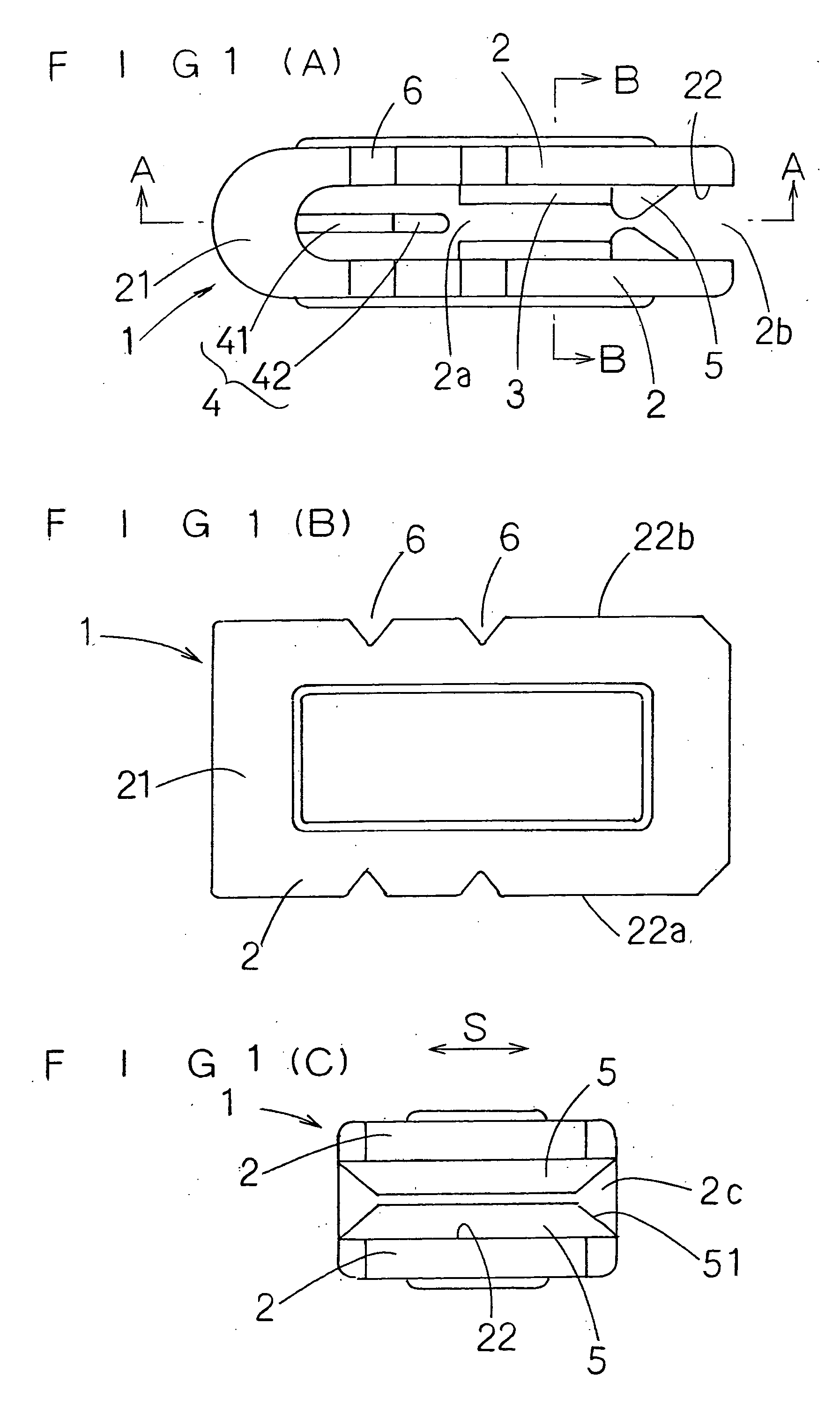
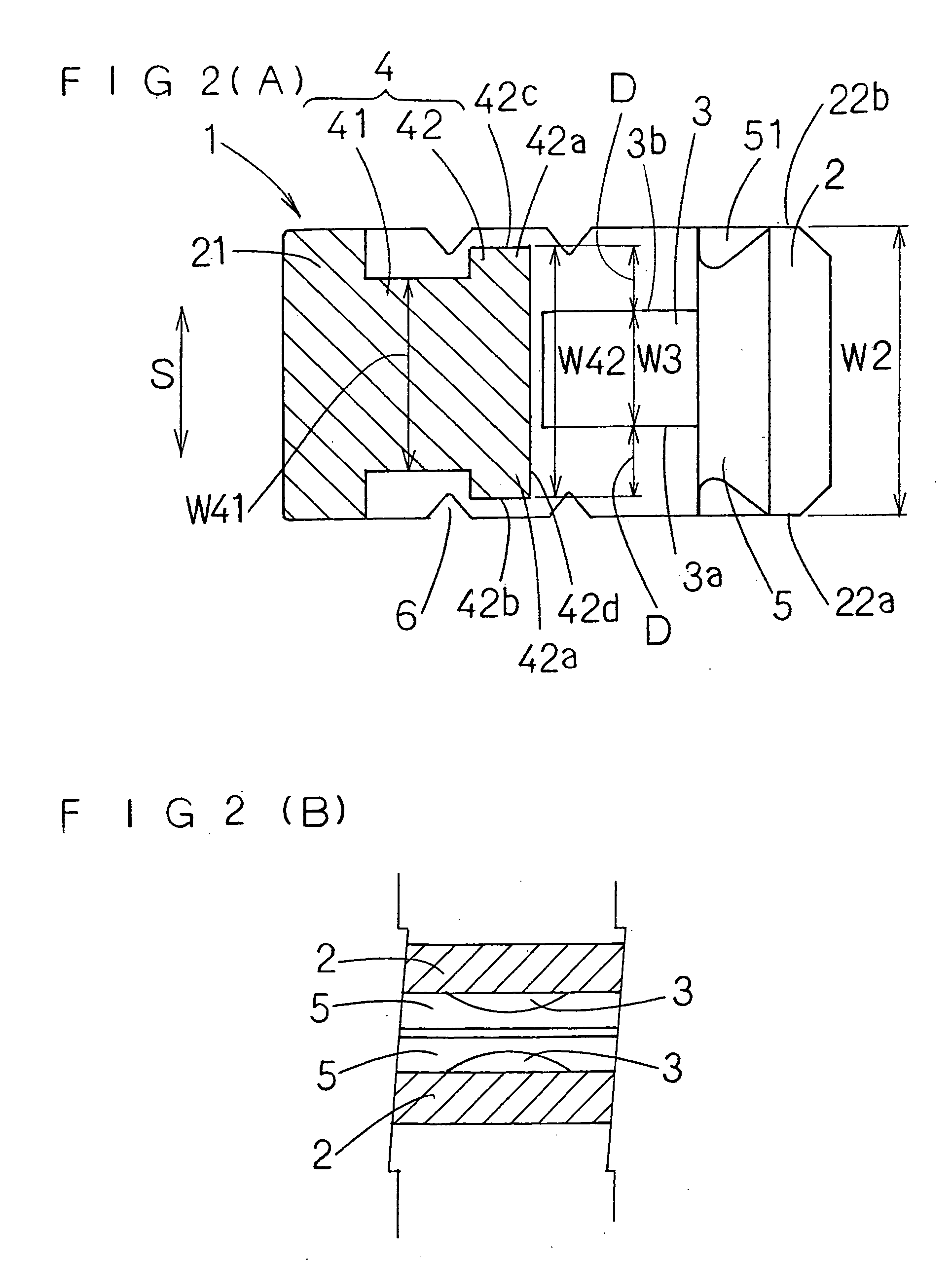
[0028] An example of an embodiment of the invention will be described below on the basis of the drawings. FIGS. 1A, 1B, 1C, 2A and 2B show a slider 1 of the embodiment, and FIGS. 3 and 4 show a state where the slider 1 is attached to a sealable storage bag B.

[0029] The slider 1 of this example is molded using, as a raw material, a hard plastic such as polypropylene. The slider 1 is configured by a joint portion 21, substantially rectangular opposing pieces 2 that include base end sides joined with the joint portion 21 so that the opposing pieces 2 are integrally disposed therewith opposing each other, and a tongue-shaped stopper 4, which is disposed so as to protrude from the joint portion 21 of the opposing pieces 2 into a space 2a between the opposing pieces 2. When the slider 1 is attached to the sealable storage bag B as shown in FIG. 3, the slider 1 is slid in a sliding direction S that is a direction along the joint portion 21 so that an opening B1 of the sealable storage bag...


PUM


Abstract

A slider for a sealable storage bag is provided that causes fastener members F which include at least one set of a convex strip portion F1 and a concave strip portion F2 disposed so as to oppose each other at inner surfaces of an opening B1 of the sealable storage bag B to be fitted together by sliding the slider 1 along the opening B1 from an outer side of the sealable storage bag B to thereby close the opening B1, the slider 1 comprising two opposing pieces 2 that are engaged with each other at a base end side and arranged with a predetermined interval therebetween at a leading end side, the opposing pieces 2 disposed at the opening B1 so as to externally cover part of the opening B1; at least one push protrusion 3 that pushes the fastener members F from the outer side of the sealable storage bag B to cause the convex strip portion F1 and the concave strip portion F2 to be fitted together so as to protrude from an inner surface 22 of at least one of the opposing pieces 2; and a tongue-shaped stopper 4 that protrudes from part of the opposing pieces 2 towards a space 2a between the opposing pieces 2, 2, with a leading end of the stopper 4 positioned further towards the base end side than the push protrusion 3, the stopper 4 having a base portion 41 disposed at the opposing pieces 2 and an expanded portion 42 disposed at the leading end side of the base portion 41, wherein a width dimension W42 of the expanded portion 42 that is a dimension along a sliding direction S exceeds a width dimension W41 of the base portion 41, the width dimension W42 being equal to or less than a width dimension W2 of the opposing pieces 2, and wherein
a dimension W3 between one end edge 3a and the other end edge 3b of the push protrusion 3 in the sliding direction S is equal to or less than the width dimension W42 of the expanded portion 42.

Description

TECHNICAL FIELD [0001] The present invention relates to the improvement of a slider for causing fastener members, which are disposed so as to oppose each other at inner surfaces of an opening of a sealable storage bag, to be fitted together by sliding the slider along the fastener members from the outer side of the sealable storage bag to thereby close the opening. BACKGROUND ART [0002] Conventionally, numerous sliders of this type have been provided. For example, the slider described in the invention disclosed in Japanese Utility Model Registration No. 3059677 is known. As shown in FIGS. 8A to 8C, the slider includes two opposing pieces 102 that are integrally provided with a base portion 101 so as to oppose each other. Fitting grooves 103, into which fastener members 202 of the sealable storage bag (see FIG. 9) are inserted to fasten the fastener members 202, are disposed in inner surfaces of the opposing pieces 102. A tongue-shaped stopper 104 is disposed between the opposing pie...

Claims


Application Information

Patent Timeline
Patent Type & Authority Applications(United States)
IPC IPC(8): B65D33/16B65D33/25
CPCY10T24/2534B65D33/2591B65D33/2508
Inventor OOTSUBO, RYOIUICHIKUSUMA, TAKEHUMI
Owner ARU
Why Eureka
Try Eureka