
Scalable multi-satellite spot beam architecture

a spot beam and multi-satellite technology, applied in the field of space segment portion of communications networks, can solve the problems of unacceptable time-consuming and expensive prospect of repointing 1 or 2 million user antennas to this backup satellite, higher cost, power and weight of connectivity satellites in general, and significant, perhaps unacceptable financial risks for these types of systems

Inactive Publication Date: 2005-09-08
LORAL SKYNET CORP
View PDF12 Cites 90 Cited by
  • Summary
  • Abstract
  • Description
  • Claims
  • Application Information

AI Technical Summary

Benefits of technology

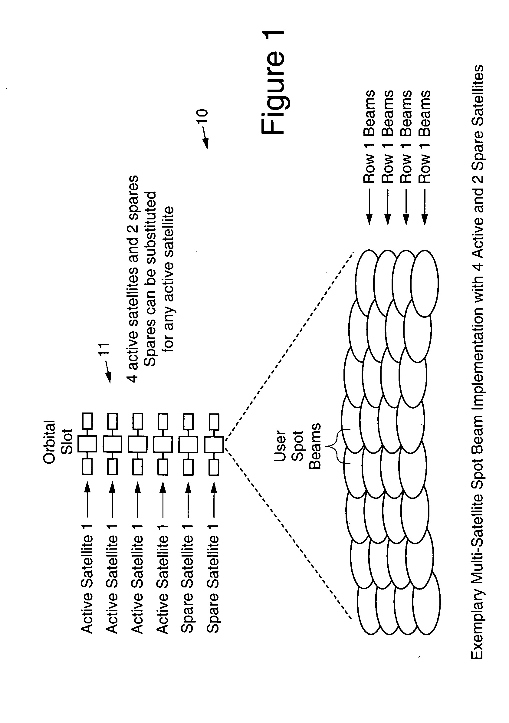
[0009] The satellites are arranged in an N+R:N configuration (also referred to as an N+R for N redundant configuration). Each satellite is similar or substantially identical in design. Each active satellite has approximately 1 / N of the total capacity (e.g., 10 Gbps / N for the example discussed in the Background section). Each of the spare satellites can provide full or partial protection for each of the active satellites, and up to “R” total satellite failures could be tolerated without losing any capacity at the orbital slot.

Problems solved by technology

The connectivity satellite in general will be higher cost, power, and weight than an access satellite for a given capacity, because of the on board switching / processing.
Although there is a very significant reduction in unit bandwidth cost for a large single spot-beam satellite compared to an area-beam satellite (perhaps by a factor of 5 or 10), the large initial capital investment and the uncertainty surrounding the take-up rate introduce substantial, and perhaps unacceptable, financial risk to these types of systems.
In the event of a total satellite failure, it is very unlikely that there would be a similar spot-beam satellite at another orbital location to which the user antennas could be re-pointed for service restoration, and the prospect of re-pointing 1 or 2 million user antennas to this backup satellite would be unacceptably time-consuming and expensive.

Method used


Image

  • Scalable multi-satellite spot beam architecture
  • Scalable multi-satellite spot beam architecture
  • Scalable multi-satellite spot beam architecture

Examples


Embodiment Construction

[0027] Referring to the drawings, FIG. 1 depicts an example of a multi-satellite 11 spot beam implementation of an architecture of a scalable geostationary satellite system 10 in accordance with the present invention. As is shown in FIG. 1, there are 4 active and 2 spare satellites 11 and either of the two spare satellites 11 can be interchanged with any of the active satellites 11.

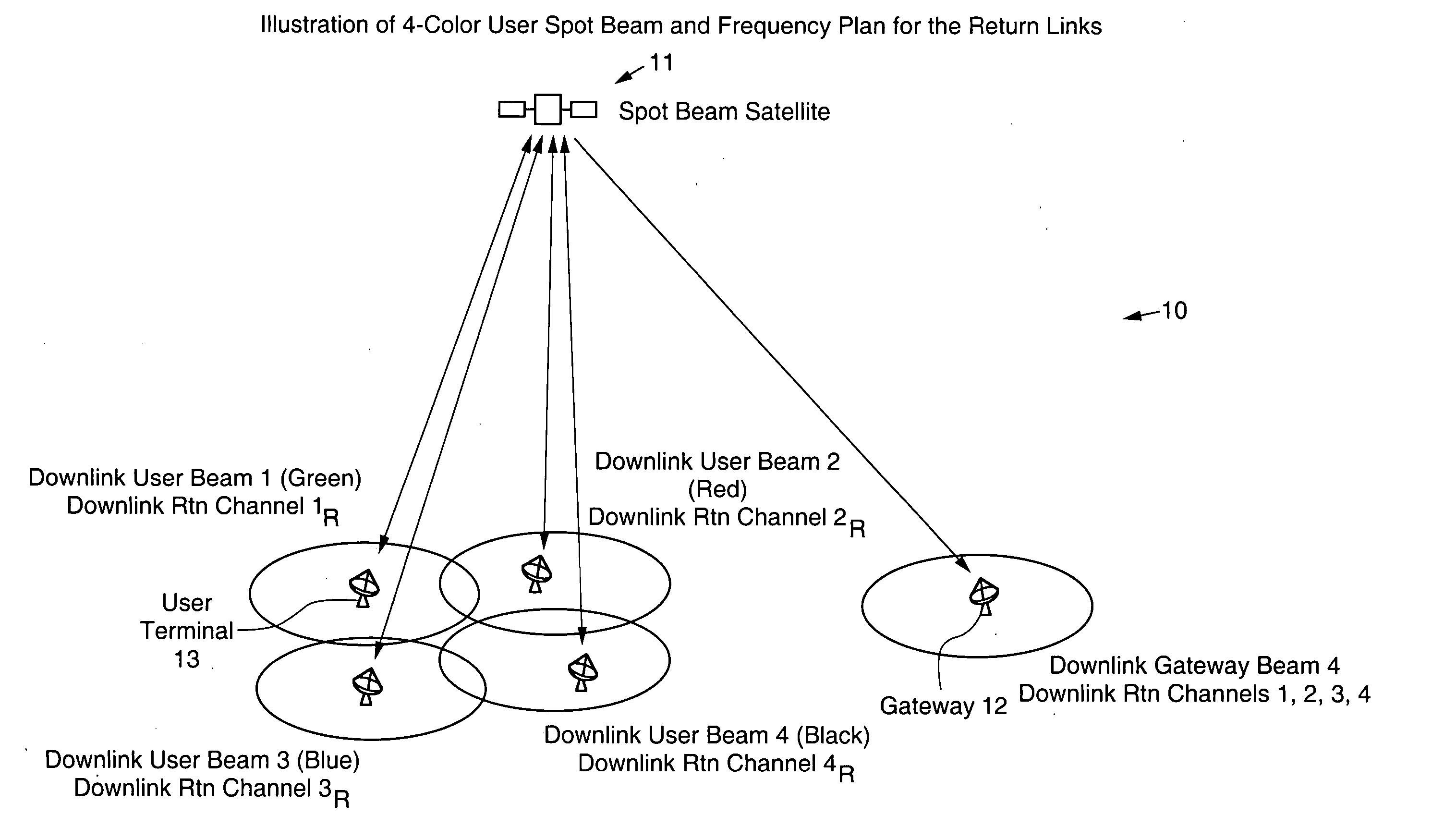
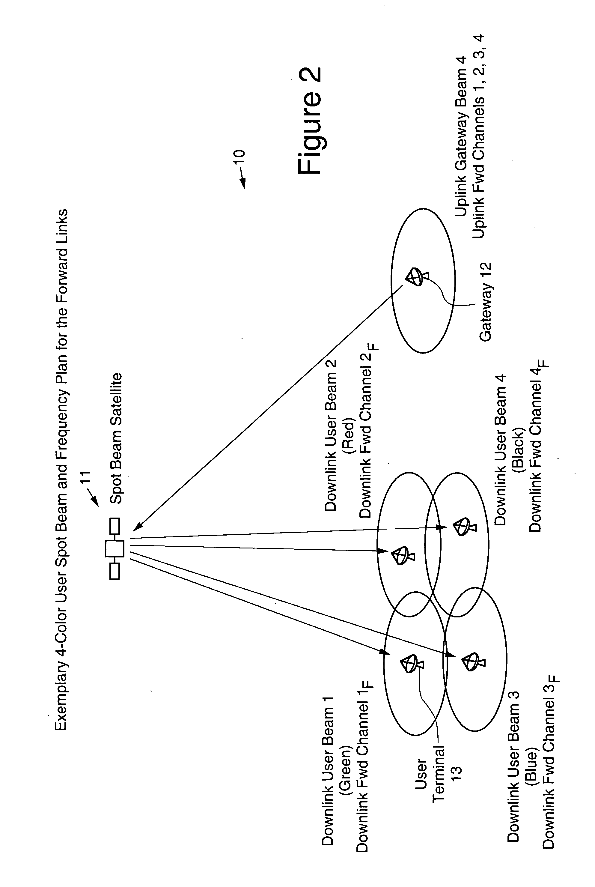
[0028]FIGS. 2 and 3 illustrate some of the general communications principles for a network, employing an access satellite 11. The forward link, also referred to as the forward channel, is used for communications FROM the gateways 12 TO the user terminals 13. In the forward communications channel, the gateway 12 would transmit to the satellite 11, via an uplink gateway beam, using the uplink frequencies allocated to the forward link, and the communications signals would be transmitted from the satellite 11 to the user terminals 13 in a downlink user beam, using the downlink frequencies allocated to the fo...


PUM


Abstract

A scalable multi-satellite spot-beam network architecture that employs a plurality (N) of relatively small (low power) active spot beam satellites and a number (R) of spare satellites, all of which are substantially similar in design, has been described. The plurality of satellites is substantially collocated at a given orbital location to provide coverage of a desired geographic area. Each active satellite has 1 / N of the total capacity of a slot, and there is significant amount of interchangeability among the active and spare satellites, enabling the spare and active satellites to provide protection against partial or full failures of any satellite or even a few (up to R) satellites. The system is scalable since a fraction of the N active satellites is required to provide capacity to the full geographic area, and additional satellites can be launched and additional gateways can be deployed to augment the network capacity. Communication devices (users) located in any of the spot beams communicate with each other and the worldwide telecommunications network via satellites and gateways of the scalable system architecture.

Description

BACKGROUND [0001] The present invention relates to the implementation of the space segment portion of communications networks, that employ geostationary spot-beam satellites for 1- or 2-way communications with user terminals 13. The invention calls for multiple collocated satellites, in which individual satellites or groups of satellites possess a high degree of interchangeability, and the space segment capacity over a fixed geographic region can be expanded with the deployment of additional (collocated) satellites. [0002] Current approaches for spot-beam satellite architectures that provide service to large geographic areas, such as the continental US (CONUS) or Europe, use a very large, high-power, satellite, one that would consume about 15 kW of prime power to provide a large number of contiguous user spot beams—on the order of 100 with diameters as small as a few hundred miles—and a substantial quantity of frequency re-use—on the order of 10 to 20 times. The systems may use sate...

Claims


Application Information

Patent Timeline
IPC IPC(8): H04B7/15H04B7/185
CPCH04B7/2041H04B7/19H04B7/1851Y02D30/70
Inventor HEDINGER, ROBERT A.CARLIN, JAMES W.GOETTLE, PETER E.
Owner LORAL SKYNET CORP
Learn More