Wrist brace having continuous loop straps and method of using the same

a technology of wrist braces and loop straps, which is applied in the field of wrist braces, can solve the problems of wrist typically involving broken bones or sprains, acute injuries, and wearers' skin abrasion or snagging, and achieve the effect of quick and easy loop slide, preventing snagging on wearers' clothing, and preventing abrasion of the wearer's skin

Inactive Publication Date: 2005-09-08
3M INNOVATIVE PROPERTIES CO
View PDF16 Cites 58 Cited by
  • Summary
  • Abstract
  • Description
  • Claims
  • Application Information

AI Technical Summary

Benefits of technology

[0018] The present invention has many advantages. The continuous loop construction of the fastening straps allows the wearer to quickly and easily slide the loop through the openings located in the wrist brace to switch between right and left handed positions. The preferred slot shape of the openings, and close fit between the slot shape and the cross-section of the continuous loop of material of the straps, maintains the orientation of the strap during reversal from a left to right handed orientation. Reversal of the hook-bearing portion when the hook bearing portion comprises at most half the outer surface of the fastening strap ensures that the hook-bearing portion is not exposed so as to prevent abrasion of the wearer's skin or snagging on the wearer's clothing. The inner surface of the strap not having non-hook bearing material ensures free sliding of the continuous loop of material within the opening defined by the sheet of material. The use of multiple straps (e.g., three straps) at different positions along a lateral edge of the sheet of flexible material allows adjustment of the amount of support provided by the wrist strap at different locations.

Problems solved by technology

Acute injuries occur most often due to sudden impacts that involve the large forces caused by an accident or from a collision during athletic activities.
Such traumatic injuries to the wrist typically involve broken bones or sprains.

Method used


Image

  • Wrist brace having continuous loop straps and method of using the same
  • Wrist brace having continuous loop straps and method of using the same
  • Wrist brace having continuous loop straps and method of using the same

Examples


Embodiment Construction

[0028] The present invention now will be described more fully hereinafter with reference to the accompanying drawings, in which some, but not all embodiments of the invention are shown. Indeed, the invention may be embodied in many different forms and should not be construed as limited to the embodiments set forth herein; rather, these embodiments are provided so that this disclosure will satisfy applicable legal requirements. Like numbers refer to like elements throughout.

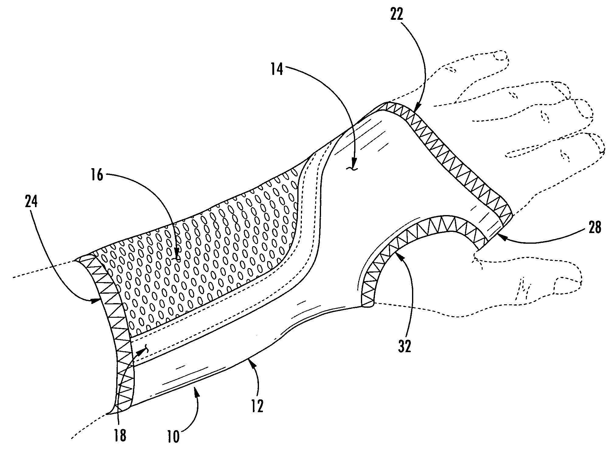
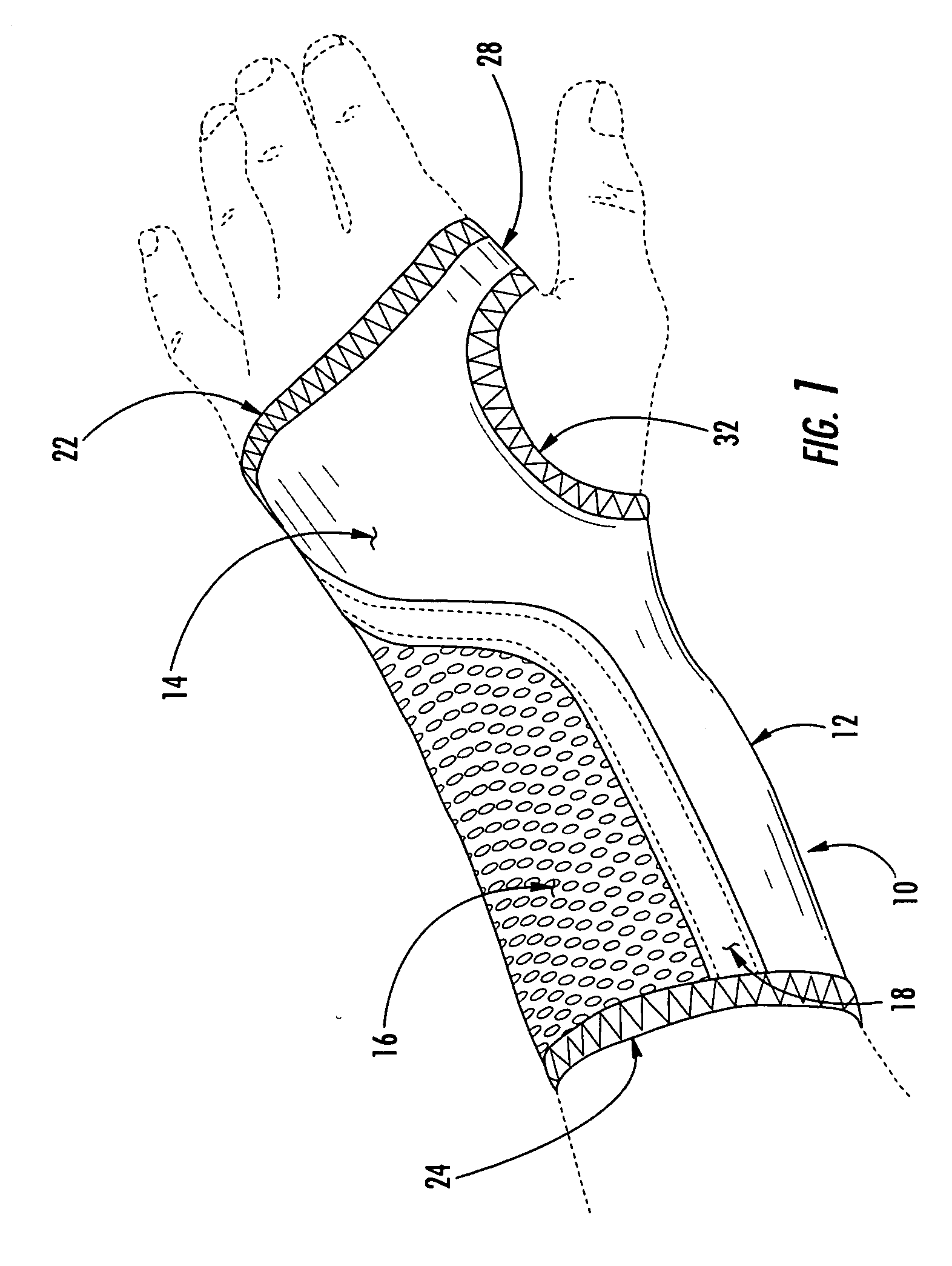
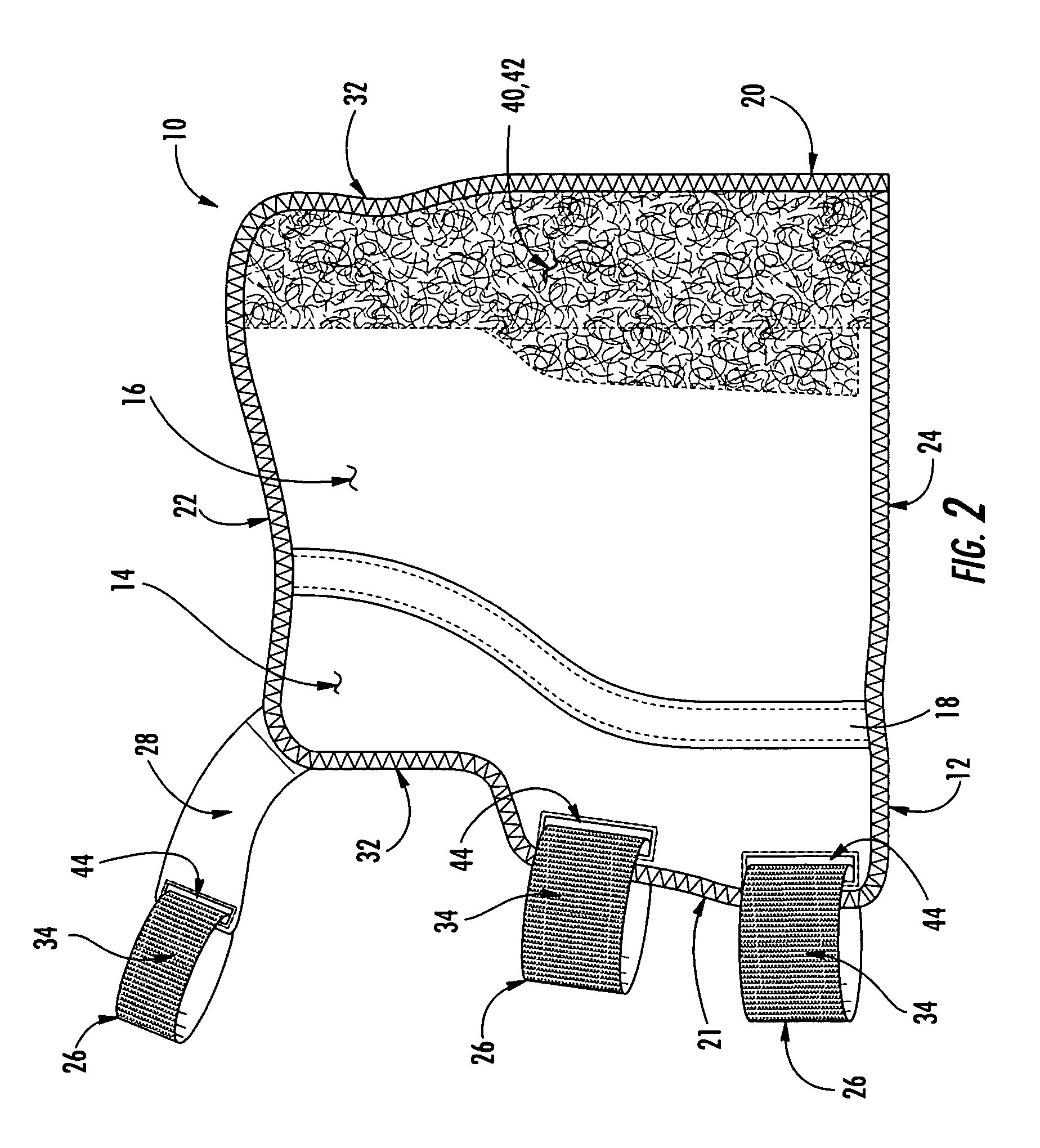
[0029] One embodiment of a wrist brace 10 of the present invention is shown in FIGS. 1 and 2. The wrist brace 10 includes a sheet 12 of material defined by edges that can extend around the wrist of a wearer. Closure of the sheet of material is secured using a plurality of fastening straps 26. Advantageously, the wrist brace 10 is reversible and can be used on either the right or left wrists of the wearer because of the reversible orientation of the sheet of material 12 and the fastening straps 26, as will be desc...


PUM


Abstract

A reversible wrist brace includes a sheet of flexible material that overlies and supports a wearer's wrist, wherein the sheet of material includes opposing surfaces each having one or more portions of loop material. The flexible sheet has at least one opening in the vicinity of a lateral edge to accommodate at least one fastening strap, such that the strap may slide within the opening. The fastening strap is a continuous loop of sheet material having an outer surface with a hook-bearing portion. The fastener is designed so as to enable a wearer to switch the wrist brace between right and left hands by orienting the hook-bearing portion so that it is coincident with the loop-bearing portion when the wrist brace is worn on either hand. The wrist brace may include a splint that may be inserted within a pocket located on the flexible material to further immobilize the wrist.

Description

BACKGROUND OF THE INVENTION [0001] 1. Field of the Invention [0002] The present invention is related to the field of orthopedic braces, and more particularly, to braces for supporting a wrist joint of a wearer. [0003] 2. Description of Related Art [0004] Wrist injuries are relatively common orthopedic injuries that occur in a range of environments, such as a home, office or outdoor environment, and can have varying levels of severity. These levels of severity are routinely grouped into two categories, chronic and acute. Acute injuries occur most often due to sudden impacts that involve the large forces caused by an accident or from a collision during athletic activities. Such traumatic injuries to the wrist typically involve broken bones or sprains. Broken bones are usually treated using complete immobilization, while sprains often only require moderate immobilization for a period of weeks depending on the grade of the sprain. Establishing immobilization early after a sprain ensures...

Claims


Application Information

Patent Timeline
Patent Type & Authority Applications(United States)
IPC IPC(8): A41F1/06A61F5/01A61F13/10A61F13/56A61F13/62
CPCA61F5/0118A61F13/108A61F13/62A61F13/622
Inventor TAYLOR, RICHARD G.MILLS, JESSICA A.
Owner 3M INNOVATIVE PROPERTIES CO
Why Eureka
Try Eureka