Handle mechanism for squat plate lifting

a technology of squat plate and handle mechanism, which is applied in the field of handle mechanism for squat plate lifting, can solve the problems of affecting one's purchase ability, negated cumbersome act, etc., and achieves the effects of convenient use, rapid and convenient plate change, and convenient loading and unloading

Active Publication Date: 2016-11-22
EMICK DANIEL W
View PDF15 Cites 21 Cited by
  • Summary
  • Abstract
  • Description
  • Claims
  • Application Information

AI Technical Summary

Benefits of technology

[0010]The present invention overcomes all drawbacks associated with prior art devices regarding the performance of wide stance squat and dead lift exercises. For starters, the weight holding member of the present invention may be rolled to weight plate and dumbbell storage stands for easy loading and unloading, then rolled into desired exercise locations with ease. This negates the cumbersome act of lugging weight plates across a crowded gym to the exercise area and barbell/squatting device locations. Additionally the present invention provides a novel “quick release” lifting means including a pair of handles which serves to further facilitate ease of use by providing for rapid and convenient plate changes uncommon to prior art offe

Problems solved by technology

This negates the cumbersome act of lugging weight plates across a crowded gym to the exercise area and barbell/squatting device locations.
This is not the case with prior art barb

Method used


Image

  • Handle mechanism for squat plate lifting
  • Handle mechanism for squat plate lifting
  • Handle mechanism for squat plate lifting

Examples


Embodiment Construction

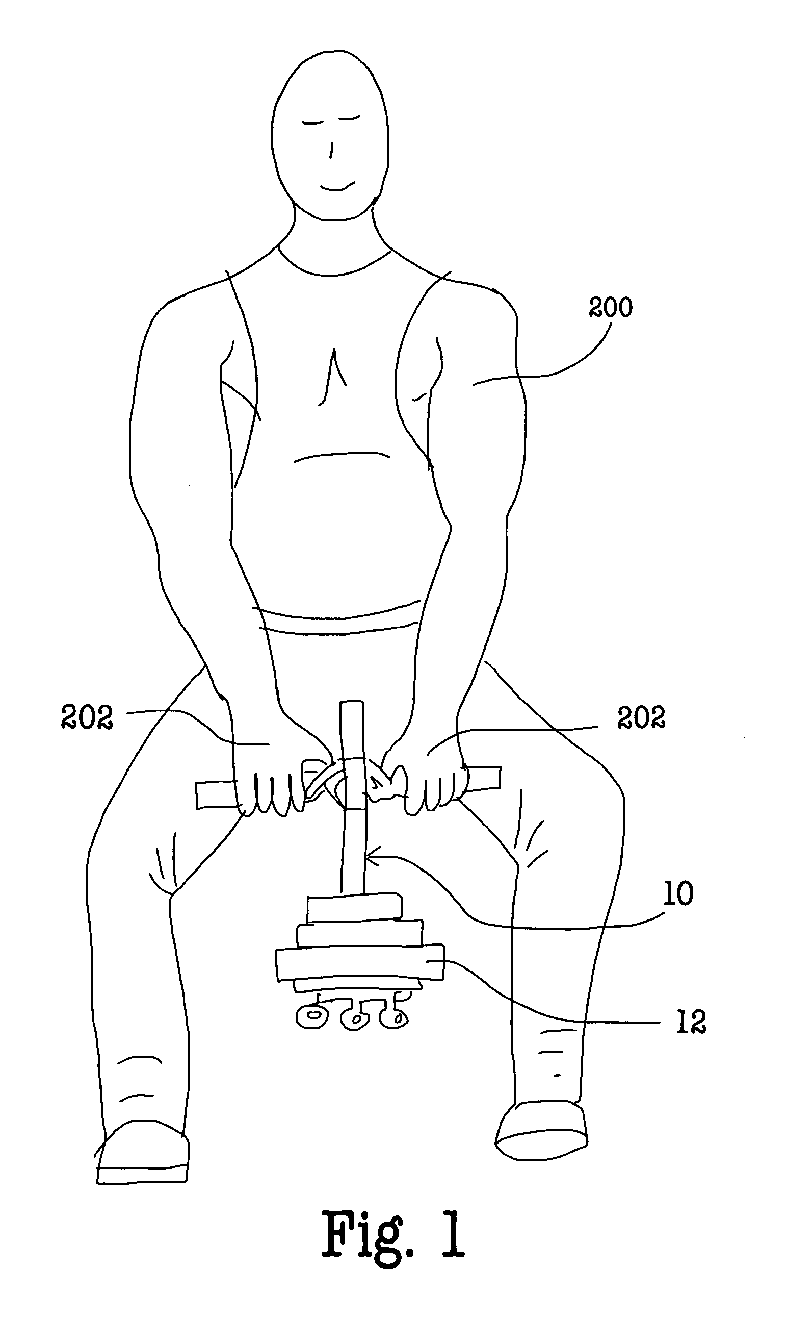
[0029]Referring to FIG. 1, a weightlifter 200 is shown lifting a handle mechanism 10 of the present invention while performing a widestance squat (otherwise known as a deadlift exercise). As can be seen, user's hands 202 are utilized to grip handles on the handle lift mechanism 10 in order to lift a desired number and weight of weight plates 12.

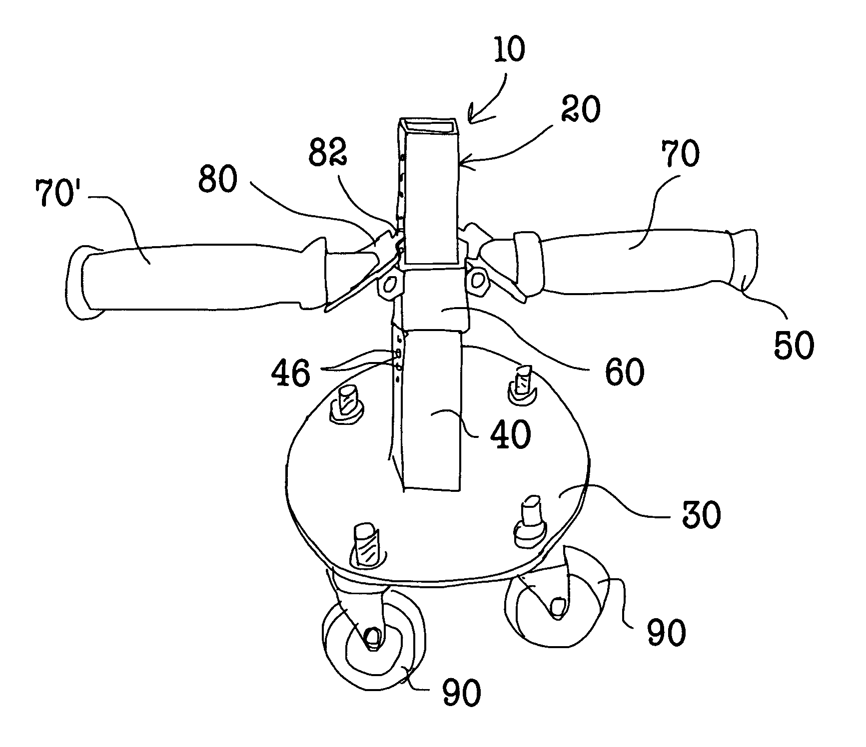
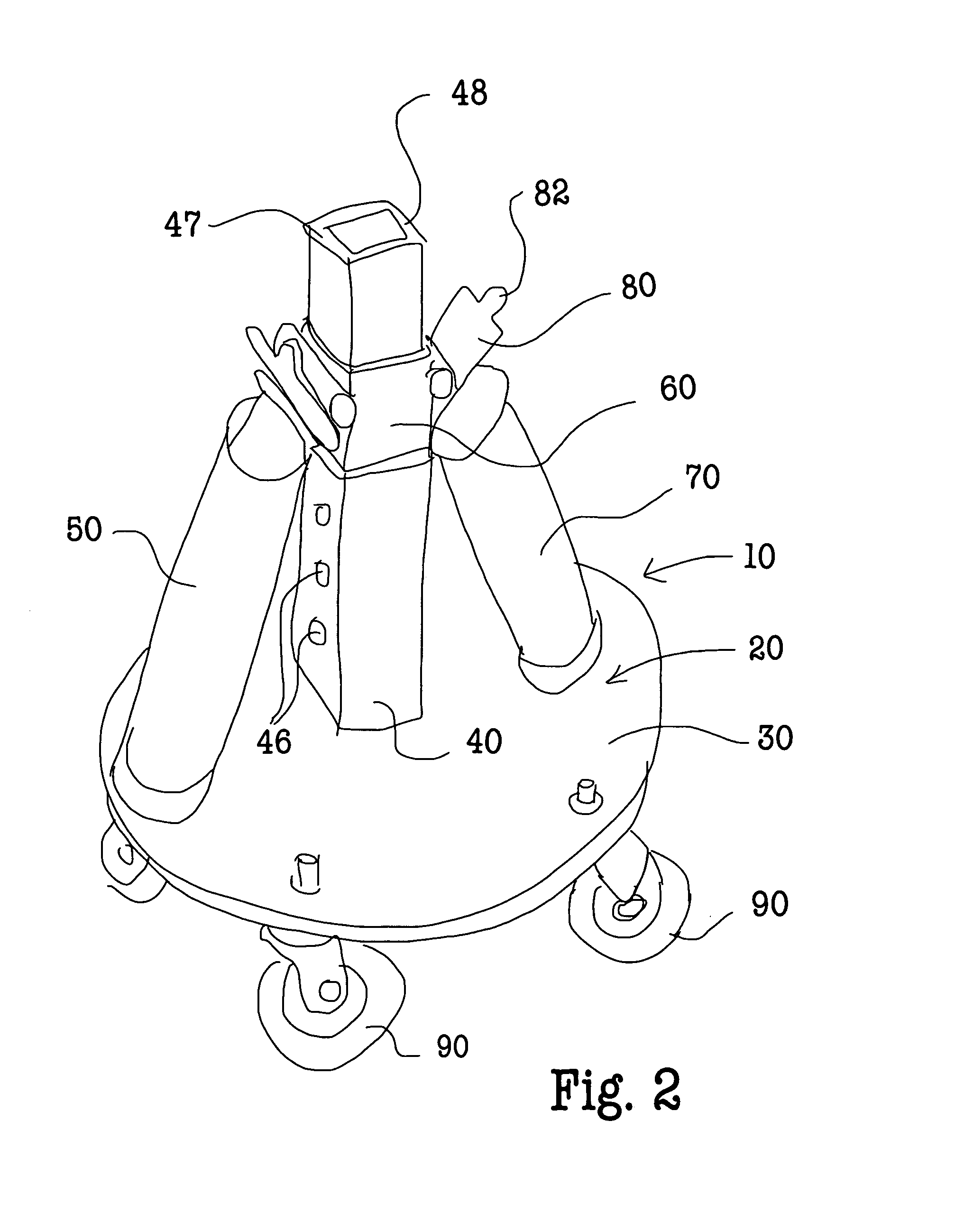
[0030]Referring to FIGS. 2-6, the handle mechanism 10 includes a weight holding member 20 which includes a baseplate 30 adapted to receive one or more weight plates 12 (see FIG. 1). The weight holding member 20 has a vertical riser tube 40 which has a first lower end 42 and a second upper end 44 (FIG. 4). The riser tube 40 has lock tab holes 46 on opposite sides 47, 48 of the riser tube 40 in a plurality of vertical locations between said lower end 42 and said upper end 44 of the riser tube 40.

[0031]A lifting means 50 is provided which has a sleeve member 60 sized and configured to slide vertically up and down on the vertical riser tube 40 an...


PUM


Abstract

A handle mechanism for squat plate lifting includes a weight holding member having a base plate adapted to receive one or more annular free weight plates. The handle mechanism includes a vertical riser tube having pairs of lock tab holes on opposite sides of the tube at a plurality of vertical locations. A lifting mechanism includes a sleeve member sized and configured to slide vertically up and down on the vertical riser tube and to be removable therefrom. A pair of handles are pivotally attached to opposite sides of the sleeve member and include a locking plate member with a locking tab attached to each handle. A user can quickly and easily slide the lifting mechanism onto the weight holding member with the handles in a lowered position and, when the handles are lifted to an uppermost horizontal position, the locking tab of each locking plate member locks into the riser tube allowing the handles to lift the entire handle mechanism. With this arrangement, without letting go of the handles, a user can successively change and lift various weight holding members of various weights.

Description

BACKGROUND OF THE INVENTION[0001]1. Field of the Invention[0002]The present invention relates to a handle mechanism for squat plate lifting. More specifically it relates to a unique lifting means including a pair of pivotally mounted handles which can be easily removed from one weight holding member and attached to a second or third etc. weight holing member, each weight holding member having differing weight plates thereon.[0003]2. Description of the Prior Art[0004]A wide stance squat or dead lift exercise is a resistance exercise that, for best results, require that weightlifters progressively increase resistance placed against targeted muscles in order to realize conditioning effects. In the case of wide stance squat / dead lift exercises, the primary targeted muscles are the legs, and more specifically the gluteus, quadriceps and adductors. Of these, the buttocks and inner thigh training effect is greatly enhanced through use of an exaggerated (wider than shoulders) foot stance wi...

Claims


Application Information

Patent Timeline
IPC IPC(8): A63B71/00A63B21/072A63B21/062A63B23/04
CPCA63B23/04A63B21/062A63B21/4033A63B21/072A63B2023/0411A63B21/0004A63B21/0618A63B21/068A63B21/0724A63B21/0728A63B22/20A63B23/0211A63B23/03525A63B23/0355A63B23/03575A63B23/0405A63B23/1209A63B23/1236A63B2208/0204A63B2208/0219A63B2208/0233A63B2210/50A63B21/4035
Inventor EMICK, DANIEL W.
Owner EMICK DANIEL W
Why Eureka
Try Eureka