

Patient interface device
a patient interface and interface technology, applied in the field of patient interface devices, can solve the problems of gas leakage around the periphery of the mask, the mask cushion may be compressed, etc., and achieve the effect of minimizing the amount of material worn and high degree of adjustability
- Summary
- Abstract
- Description
- Claims
- Application Information
AI Technical Summary
Benefits of technology
Problems solved by technology
Method used
Image

Examples
first embodiment
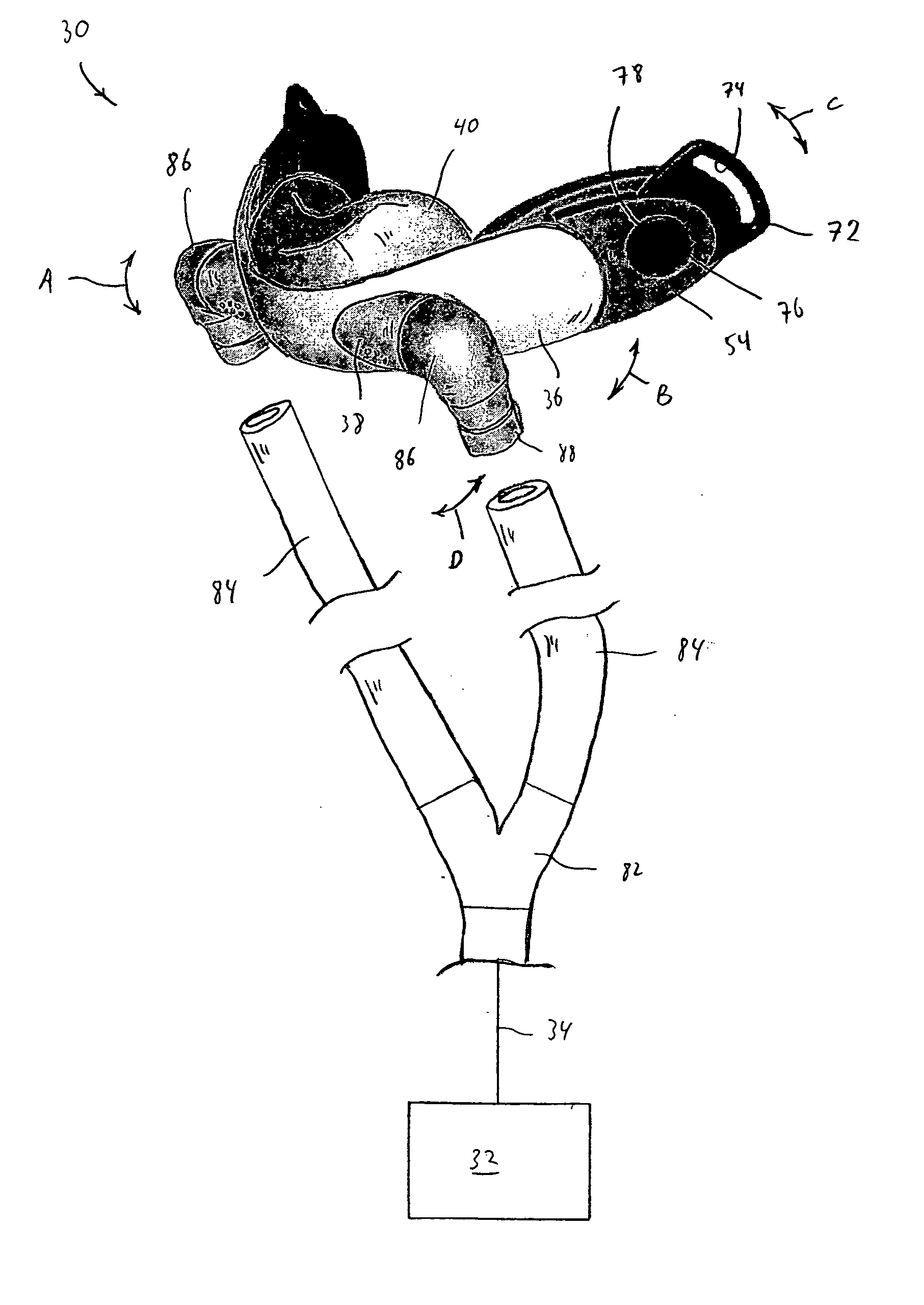
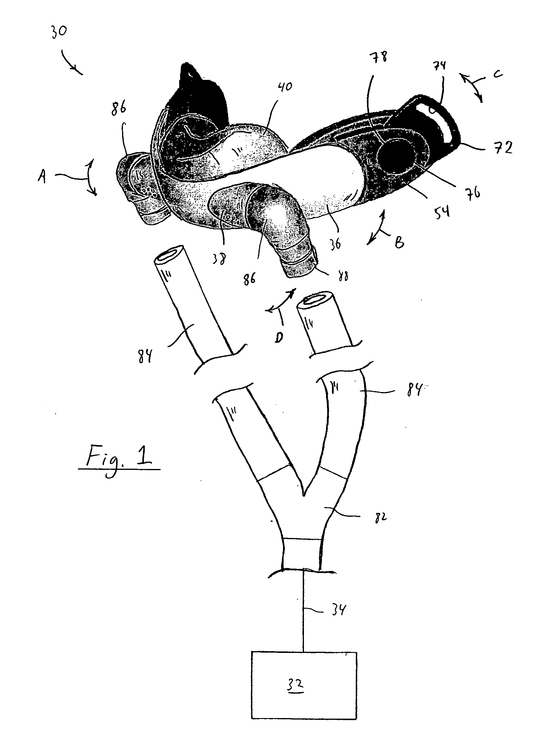
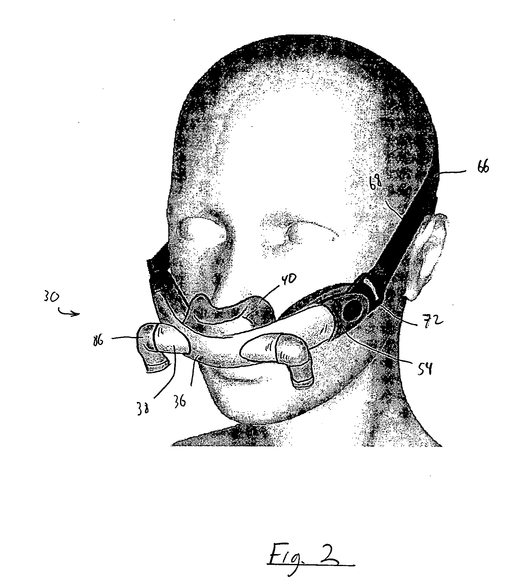
[0058]FIGS. 1-4 illustrate a patient interface device 30 according to the principles of the present invention. Patient interface device 30 is shown schematically connected to a pressure support system 32 via a patient circuit 34, which communicates gas from the pressure support system to the patient interface device. Pressure support system 32 is any conventional ventilation or pressure support system.
[0059] Examples of such pressure support systems include, but are not limited to: a ventilator, continuous positive airway pressure (CPAP) device, or a variable pressure device, e.g. an auto-titrating device, proportional assist ventilation (PAV®) device, proportional positive airway pressure (PPAP®) device, C-Flex™ device, Bi-Flex™ device, or a BiPAP® device manufactured and distributed by Respironics, Inc. of Pittsburgh, Pa., in which the pressure provided to the patient varies with the patient's respiratory cycle so that a higher pressure is delivered during inspiration than during ...
second embodiment
[0076]FIGS. 5-12 illustrate a patient interface device 100 according to the principles of the present invention. Patient interface device 100 is similar in many respects to patient interface device 30 discussed above. A key difference resides in type of sealing assembly 102 used to communicate a flow of gas from support member 104 to the patient's airway. In the present embodiment, sealing assembly 102 is a nasal-cannula type of patient interface, including a pair of prongs 106 extending from a base portion 108. Openings 110 are provided in prongs 106 to communicate the interior chamber of each prong with a patient's nostril.
[0077] It should be noted that the present invention contemplates that the sealing assembly can include other types, styles, sizes, and shapes of patient interface devices in place of the nasal cushion or nasal prongs illustrated and described above. For example, the present invention contemplates providing a sealing assembly that communicates with the nasal pas...
third embodiment
[0089]FIGS. 17 and 18 show a headgear attachment assembly 174 (shown unassembled) suitable for use with the patient interface device of the present invention. Headgear attachment assembly 174 includes a headgear clip 176 that inserts into a slot 178 defined in a pad support 180. Headgear clip 176 includes a tab 182 that inserts into a slot 184 provided in pad support 180. A cover member 186 on pad support 180 deflects slightly to allow the clip to insert and engage within the slot in the pad support. Cover member 186 holds the headgear clip such that tab 182 remains engaged in slot 184. To detach the headgear clip from the pad support, a slight deflecting force is applied to cover member 186, for example, by pulling away from the patient on the exposed end of the headgear clip. The force deflects the cover member outward, widening slot 184, so that tab 182 can disengage from the slot.
PUM
 Abstract
Description
Claims
Application Information