Emergency lighting function illumination appliance

a technology of illumination appliance and emergency lighting, which is applied in the direction of emergency power supply arrangement, process and machine control, instruments, etc., can solve the problems of difficulty in integrating, difficulty in distinguishing between power outage and user switch off, and lack of economic and convenient technology in the conventional market, so as to save the expense of additional purchasing

Inactive Publication Date: 2005-09-15
KUO CHAO TUNG
View PDF3 Cites 4 Cited by
  • Summary
  • Abstract
  • Description
  • Claims
  • Application Information

AI Technical Summary

Benefits of technology

[0009] The objective of the invention herein is to provide an emergency lighting function illumination appliance to save the expense of additionally purchasing emergency lighting.
[0011] The present invention provides for the integration of an emergency illumination device and an ordinary illumination device into one unit. The most attractive part of this invention is that the circuit layout of the building needs not to be modified. Thus, to reduce expenditures, increase lighting area coverage, and facilitate evacuation efficiency.

Problems solved by technology

Such emergency lighting is only placed along hallways, stairs, passageways, and other ordinarily illuminated areas that must be passed through during evacuations to highlight their locations and, therefore, the illuminated areas are limited and, furthermore, due to their wall-mount design, light is only directed onto walls, which is a further curbs area coverage.
The most difficult aspect of integration is how to differentiate between power outage and user switch offs.
The market solution approach is to use a three-wire circuit for control (building circuits must be re-configured), a few utilize remote controllers, and some use cords to operate switches; in short, the conventional market does lacks a technology that is economical and convenient.

Method used


Image

  • Emergency lighting function illumination appliance
  • Emergency lighting function illumination appliance
  • Emergency lighting function illumination appliance

Examples


Embodiment Construction

[0018] The invention herein utilizes fluorescent lamp technological content, features, and functions. To enable a further understanding, the brief description of the drawings is followed by the detailed description of the most preferred embodiment of the invention herein.

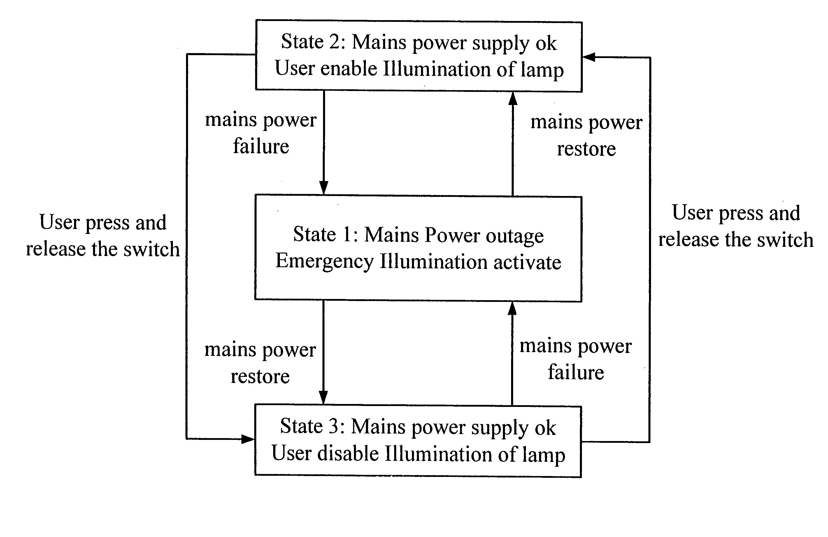
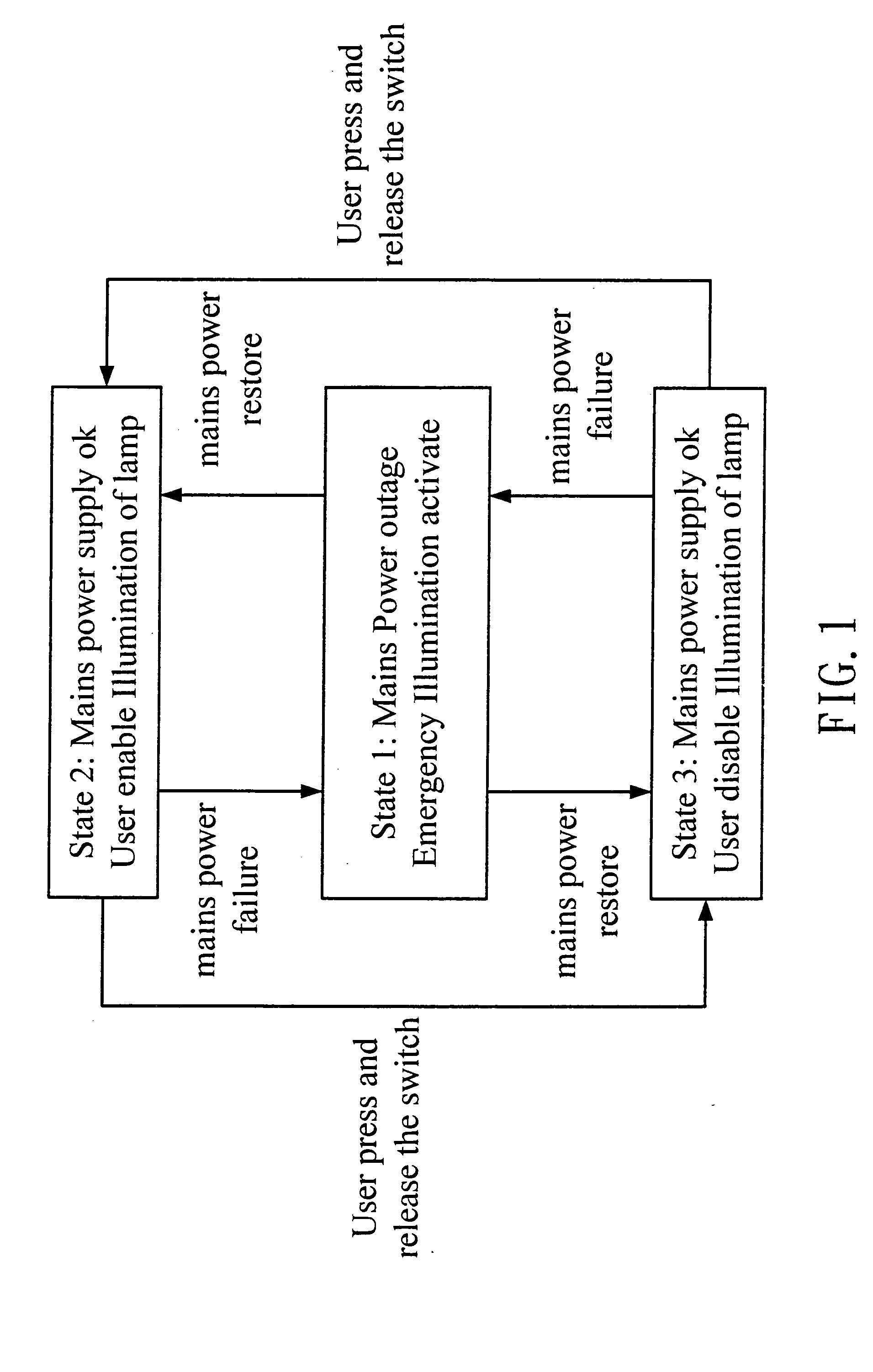
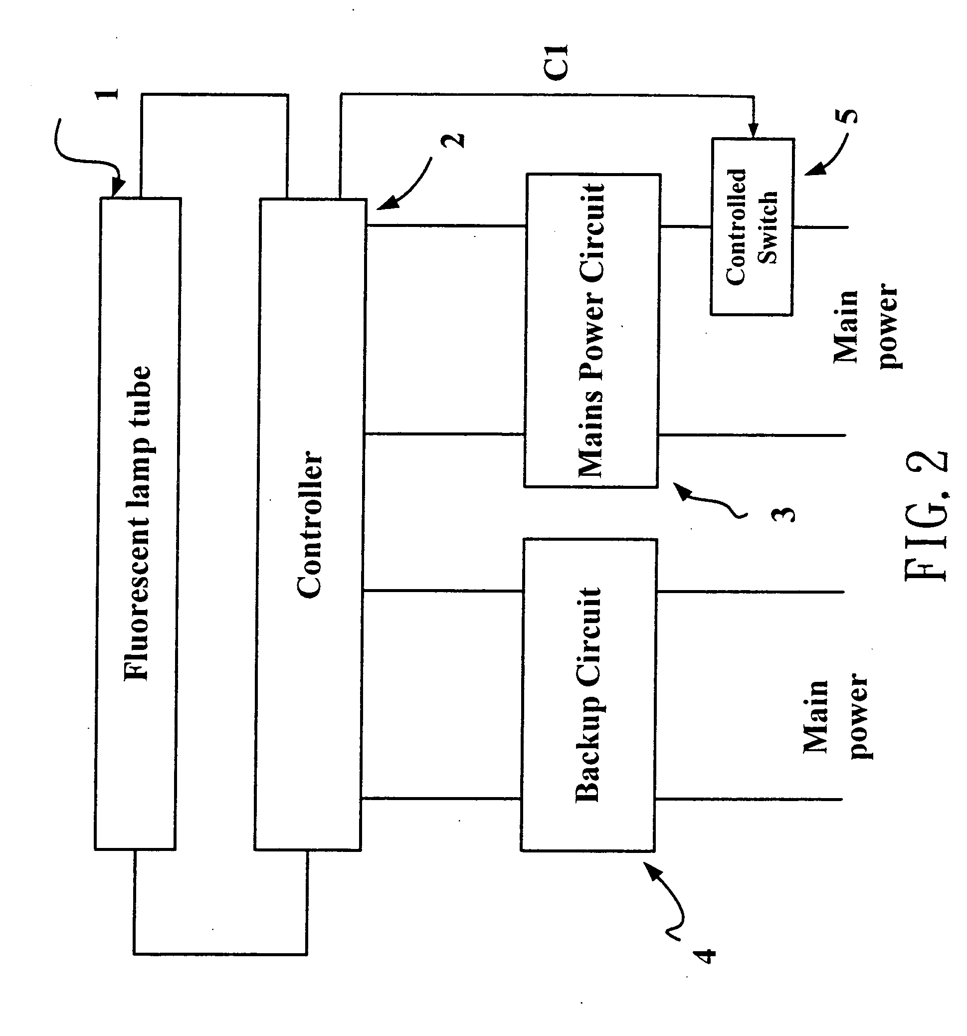
[0019] When conventional fluorescent lamp available on the market normally utilize commercial mains electricity, the user toggles a switch to control fluorescent lamp continuity or discontinuity with power and thereby effectively achieve lamp illumination and extinguishment; however, the design of conventional fluorescent lamp is such that they are incapable of distinguishing between a normal power and a power outage situation; to integrate an emergency illumination device and an ordinary illumination device into one unit, under normal mains power conditions, the design herein utilizes a special device, the controller of the invention herein, which after processing generates different level electrical signals to th...


PUM


Abstract

An emergency lighting function illumination appliance comprised of a fluorescent lamp tube, a controller, a mains power circuit capable of processing mains electricity for lighting, and a backup circuit that provides for a reserve power source. By integrating these devices, renovation of existent wiring is not required for installation. When mains electricity is normally supplied, an ON-OFF switching approach controls the illumination and extinguishment of the fluorescent lamps, but during mains electricity failures, a power circuit automatically shifts to a backup circuit that furnishes reserve power to provide for emergency lighting. Furthermore, when mains electricity supply is restored, the power circuit is automatically shifted to the mains power circuit such that ordinary lighting function is once again reliant on mains electricity.

Description

BACKGROUND OF THE INVENTION [0001] 1) Field of the Invention [0002] The invention herein relates to emergency lighting equipment, specifically an emergency lighting function illumination appliance that integrates ordinary lighting and emergency lighting into a single piece of equipment. [0003] 2) Description of the Prior Art [0004] Conventional emergency lighting equipment is a type of appliance that continues to provide illumination during failures of normal power (commercial mains electricity) distribution with the purpose of maintaining minimal visibility in homes, work places, and shelter passageways to thereby enable a short period of time to conclude work or facilitate evacuation guidance. Evacuation guidance devices includes exit indicator lights over safety doors and various hallway direction signs, their installation allowing identification of evacuation passageways and safety door locations in the dark. As living quality has risen in recent years, building design has in ad...

Claims


Application Information

Patent Timeline
Patent Type & Authority Applications(United States)
IPC IPC(8): H02J9/06H05B41/285
CPCH02J9/065Y02B20/186H05B41/2853Y02B20/00
Inventor KUO, CHAO-TUNG
Owner KUO CHAO TUNG
Why Eureka
Try Eureka