Lay-in electrical connector

Inactive Publication Date: 2005-09-15
ILSCO
View PDF12 Cites 31 Cited by
  • Summary
  • Abstract
  • Description
  • Claims
  • Application Information

AI Technical Summary

Benefits of technology

[0007] The first bore and the transformer stud may include complementary threads such that the first bore threadingly engages the transformer stud. Alternatively, the bore may be sized so as to provide a slip fit connection between the body member and the transformer stud. The body member may further include a binding screw capable of being tightened to inhibit the withdrawal of the transformer stud from the first bore.
[0008] In another embodiment in accordance with the invention, the conductor-receiving channels are arranged in two rows along the body member to provide twice the number of channels per unit length of body member while also providing a lay-in feature. The first row of conductor-receiving channels are superimposed above the second row of conductor-receiving channels. The body member may include

Problems solved by technology

Due to the relatively large size of the electrical conductors distributing power from the secondary side of a transformer and the inability to bend or otherwise manipulate the conductor into the ports on the stud mount connectors, electrical

Method used


Image

  • Lay-in electrical connector
  • Lay-in electrical connector
  • Lay-in electrical connector

Examples


Embodiment Construction

[0020] Although the invention will be described next in connection with certain embodiments, the invention is not limited to practice in any one specific type of lay-in style electrical connector. It is contemplated that the principles of the invention can be used with a wide variety of lay-in style electrical connectors. The description of the invention is intended to cover all alternatives, modifications, and equivalent arrangements as may be included within the spirit and scope of the invention as defined by the appended claims. In particular, those skilled in the art will recognize that the components of the invention described herein could be arranged in multiple different ways.

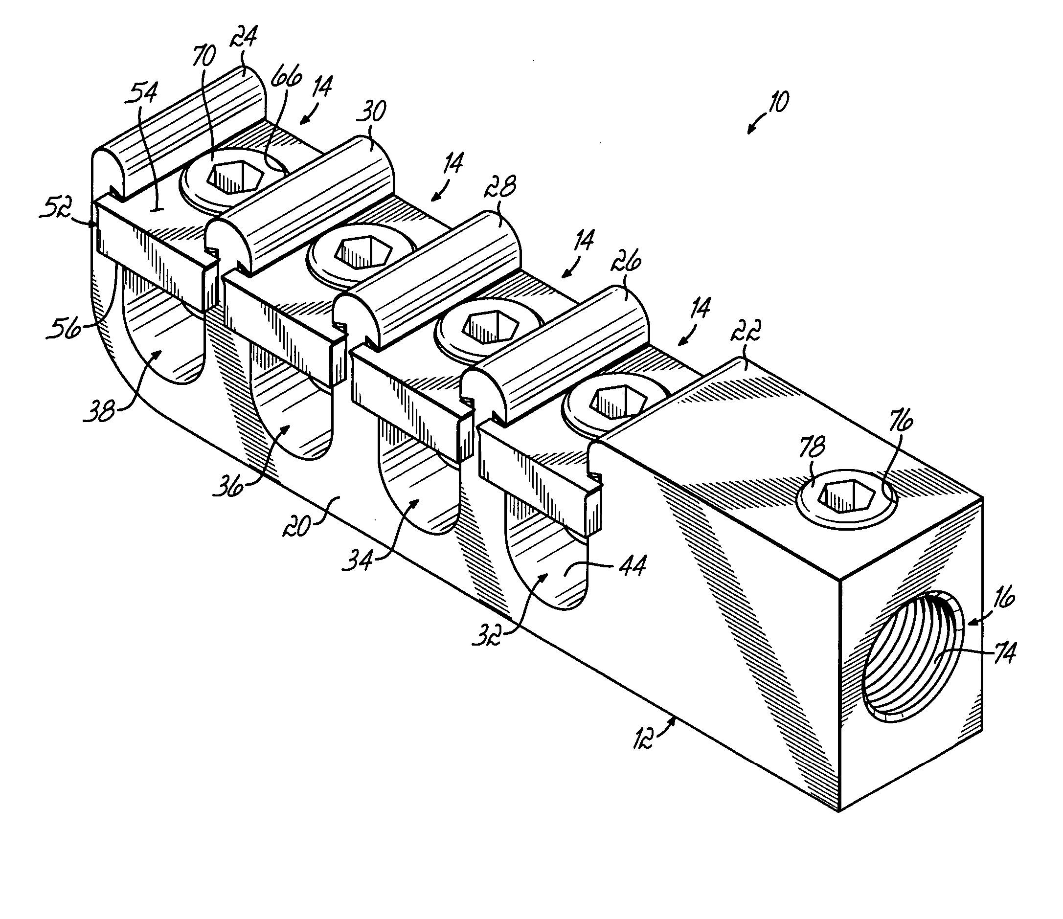
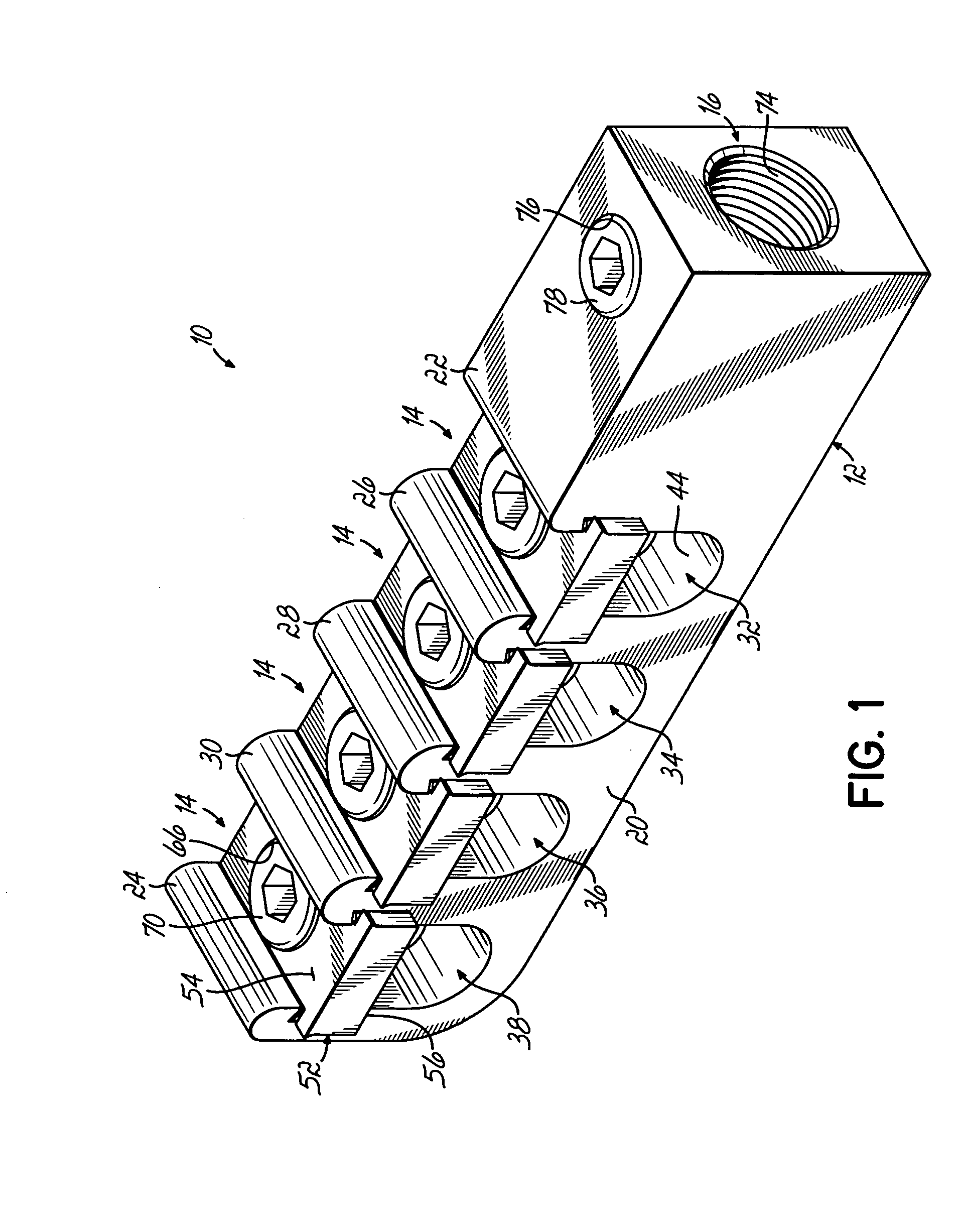
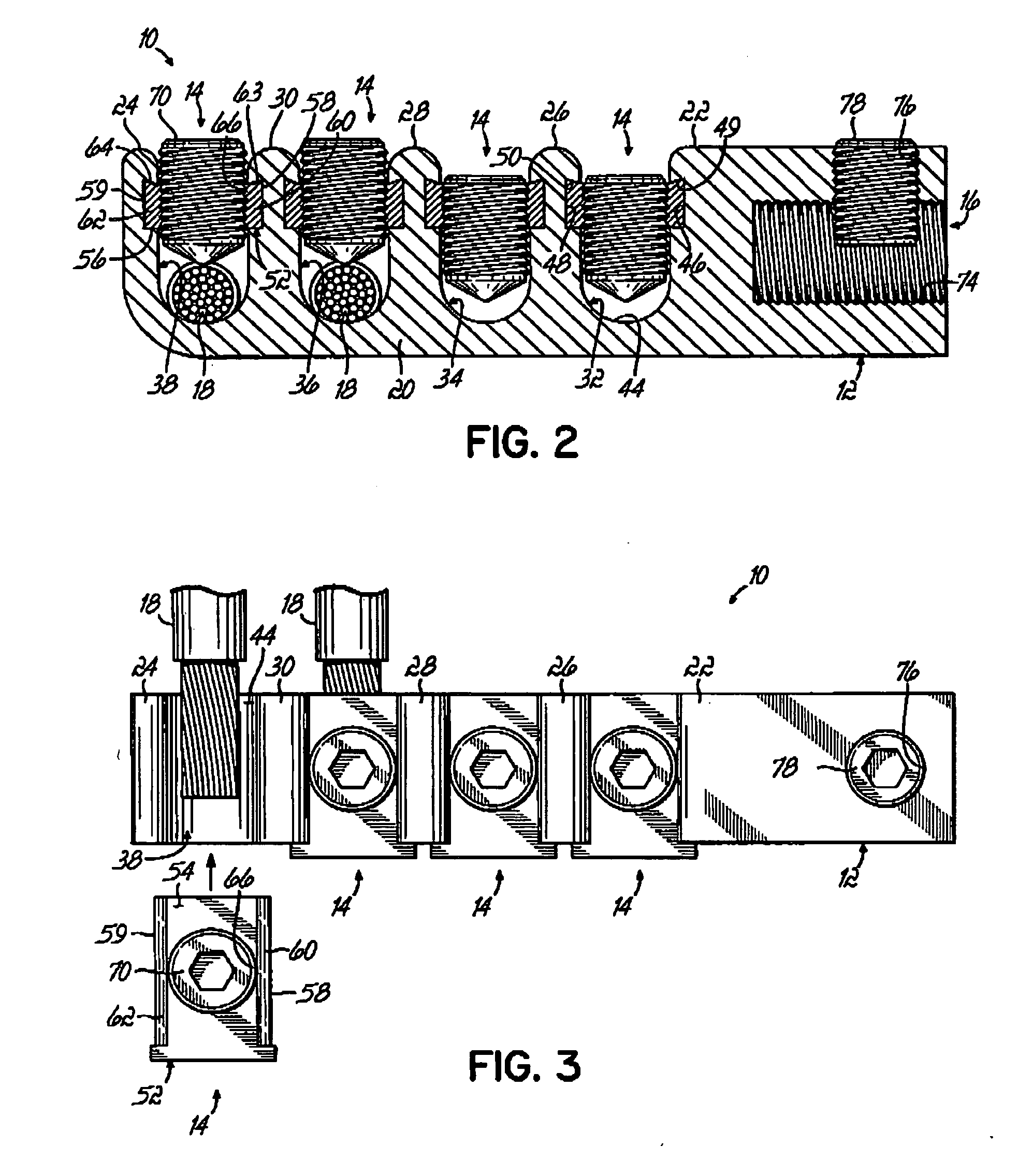
[0021] With reference to FIGS. 1-3, a lay-in electrical connector 10 of the invention is an assembly including a body member or lug body 12, multiple cap members or lug caps 14 removably coupled with the lug body 12, and a bore 16 formed in the lug body 12. The bore 16 is used to mount the electrical co...


PUM


Abstract

A stud mounted lay-in electrical connector having a lug body with multiple dividing walls defining multiple conductor-receiving channels, multiple lug caps each associated with one of the conductor-receiving channels, and a bore formed in the body member adapted to be releasably coupled with a transformer stud. The conductor-receiving channels may be configured in two rows to provide twice the number of channels per length of body member. The connector may also comprise a body member having a first portion including a bore adapted to connect to a transformer stud and a second portion carrying the multiple conductor-receiving channels, the second portion removably coupled to the first portion.

Description

FIELD OF THE INVENTION [0001] The present invention relates to electrical connectors and, in particular, to lay-in electrical connectors. BACKGROUND OF THE INVENTION [0002] Lay-in electrical connectors are frequently used for securing large gauge conductors that are stiff and difficult to handle as compared with smaller diameter conductors that are readily deformed and contorted for securement. Lay-in electrical connectors generally include a lug body having a channel-shaped wireway, a top screw-threaded lug cap received and captured within the wireway, and a binding screw extending through the lug cap to be tightened against one or more conductors positioned in the wireway. The wireway is defined by opposed upstanding walls each having an inwardly-oriented groove that captures a corresponding one of opposite side flanges provided on the lug cap. The grooves of the wireway cooperate with the side flanges of the lug cap to resist upward movement of the lug cap as the binding screw is...

Claims


Application Information

Patent Timeline
IPC IPC(8): H01R11/09
CPCH01R4/36H01R11/09H01R11/07
Inventor RIZZO, DAVID J.VIDIC, JAMES S.
Owner ILSCO
Why Eureka
Try Eureka