Surgical device for implanting a total hip prosthesis

a surgical device and hip technology, applied in the field of surgical devices for implanting a total hip prosthesis, can solve the problems of prolonging the duration and cost of hospitalization of patients

Inactive Publication Date: 2005-09-15
CORIN
View PDF18 Cites 255 Cited by
  • Summary
  • Abstract
  • Description
  • Claims
  • Application Information

AI Technical Summary

Benefits of technology

[0008] By using the device according to the invention, the surgeon may, during the surgery proper, compare the cone of mobility of the prosthesis associated with the prosthesis to be implanted with the different measured positions of the femoral prosthetic direction considered, these positions preferably corresponding to extreme articular configurations of the operated patient's hip, namely articular configurations combining the movements of flexion / extension, of abduction / adduction and / or of medial / lateral rotation, such as for example the cross-legged configuration which combines the movements of flexion, of abduction and of lateral rotation. During the surgical operation of fitting the prosthesis, the surgeon then chooses a preferential direction to implant the acetabulum of the prosthesis, allowing the subsequent manipulation of the prosthesis up to in these extreme articular configurations without risking dislocation thereof. In other words, the surgical device according to the invention allows the surgeon to determine this preferential direction of implantation, or a plurality of these preferential directions, that the surgeon will then respect at the end of the surgical operation to implant the acetabulum of the prosthesis.

Problems solved by technology

This method therefore necessitates very considerable data processing means which are expensive, as well as a large amount of pre-operative data, which prolongs the duration and cost of hospitalization of the patient.

Method used


Image

  • Surgical device for implanting a total hip prosthesis
  • Surgical device for implanting a total hip prosthesis
  • Surgical device for implanting a total hip prosthesis

Examples


Embodiment Construction

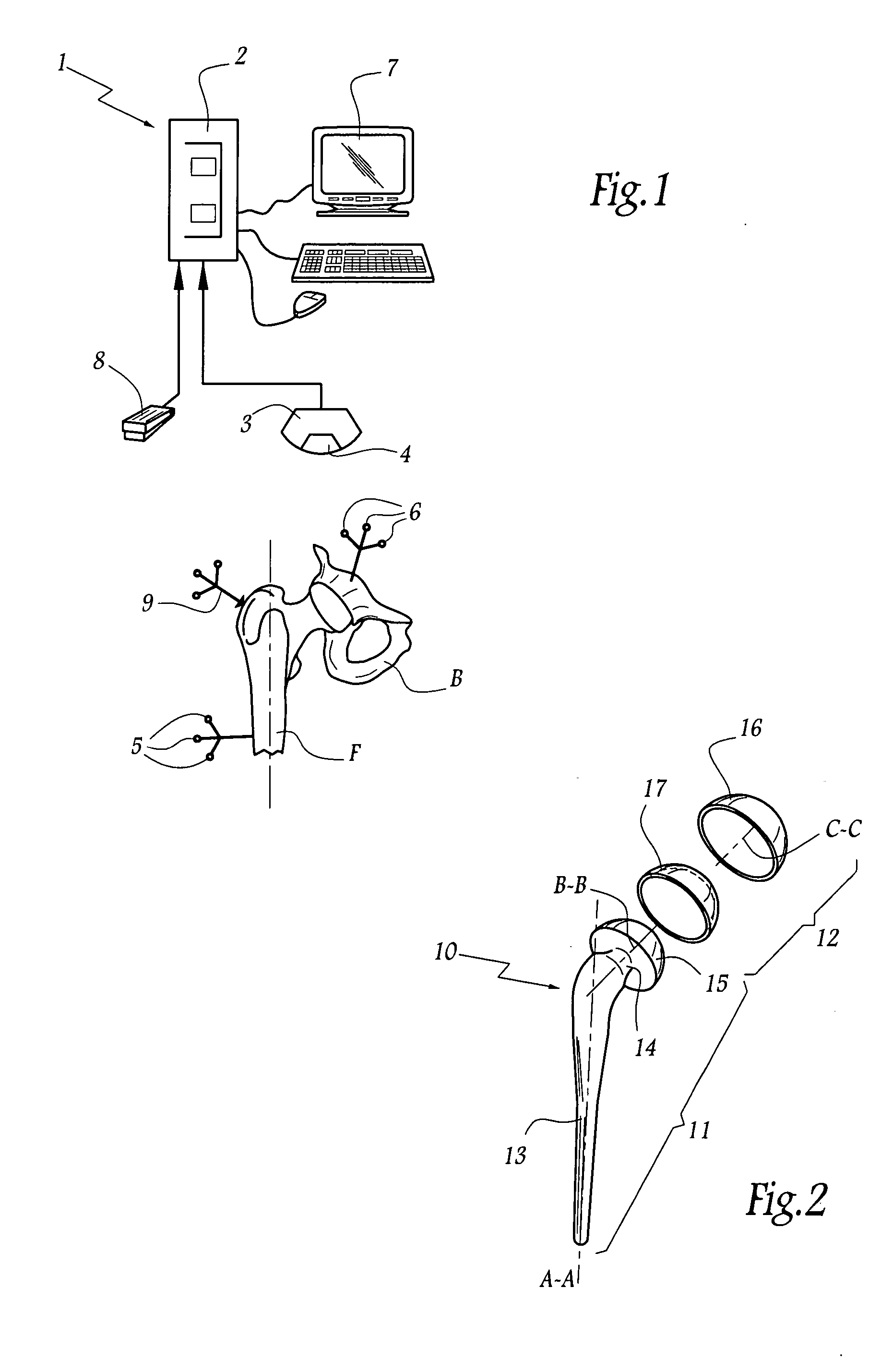
[0034] Referring now to the drawings, the surgical device 1 of FIG. 1 comprises a computer 2 associated with a unit for emitting and receiving infra-red radiations. This unit comprises a sensor 3 connected to the computer and a source of infra-red emission 4 covering the operative field in which is partly shown a hip of a patient to be treated. The hip comprises the upper part of a femur F and a corresponding part of the pelvic bone B.

[0035] In order to allow the computer 2 to locate the bones of the femur F and of the pelvis B in space, the device 1 comprises respective groups of markers 5 and 6 which passively return the infra-red radiation in the direction of the sensor 3. Each group of markers 5 or 6 forms a three-dimensional marking system allowing the computer 2 / sensor 3 assembly to follow in space the respective displacements of the femur and pelvis. As the use of such markers is well known in the domain of orthopaedics, they will not be described here in greater detail.

[00...


PUM


Abstract

The surgical device according to the invention comprises both means for per-operative measurement and for memorization of a plurality of positions of a given femoral prosthetic direction and means for per-operative comparison of these positions with the cone of mobility of the prosthesis to be implanted, the position of the axis of revolution of this cone being, during the implantation of the prosthesis, adjustable with respect to the zone of the pelvis where the implantation of an acetabulum of the prosthesis is provided. By using this device, the surgeon can easily and rapidly determine, in the course of the surgical operation, a preferential direction for implanting the prosthetic acetabulum in order to reduce the subsequent risks of dislocations of the implanted prosthesis.

Description

FIELD OF THE INVENTION [0001] The present invention relates to a surgical device for implanting a total hip prosthesis. BACKGROUND OF THE INVENTION [0002] A total hip prosthesis conventionally comprises, on the one hand, a femoral part constituted by a stem, at one end of which is fixed a femoral head defining a globally spherical convex articular surface and, on the other hand, a cotyloid part to be fixed to the bone of the pelvis, comprising for example a cotyloid metal cup in hemispherical form, inside which is housed an insert made of plastics material or ceramics in which the femoral head is articulated. [0003] When such a total hip prosthesis is fitted, the surgeon implants, on the one hand, the femoral stem inside a cavity hollowed out longitudinally in the bone of the femur and, on the other hand, the cotyloid part of the prosthesis in a globally hemispherical cavity hollowed out in the bone of the pelvis. The direction of implantation of the femoral stem in the bone of the ...

Claims


Application Information

Patent Timeline
Patent Type & Authority Applications(United States)
IPC IPC(8): A61B17/56A61B17/88A61B17/92A61B19/00A61F2/00A61F2/30A61F2/32A61F2/34A61F2/36A61F2/46G06T7/00
CPCA61B19/50G06T2207/30008A61B2019/502A61B2019/505A61B2019/5255A61B2019/5272A61F2/34A61F2/36A61F2/3662A61F2/4607A61F2/4609A61F2/4657A61F2/4684A61F2002/30616A61F2002/3208A61F2002/3233A61F2002/3611A61F2002/3625A61F2002/4623A61F2002/4631A61F2002/4632A61F2002/4633A61F2002/4663A61F2002/4668A61F2002/4681A61F2002/4697A61F2250/0064A61F2310/00011G06T7/0042A61B19/5244A61F2/4603A61F2002/4696A61B34/10A61B34/20A61B2034/102A61B2034/105A61B2034/2055A61B2034/2072G06T7/73
Inventor LAFFARGUE, PHILIPPEMIGAUD, HENRIPUGET, JEANGIRAUD, FRANCOISTABUTIN, JACQUES
Owner CORIN
Why Eureka
Try Eureka