Non pull cord operated blind structure

a non-pull cord and blind technology, which is applied in the direction of door/window protective devices, building components, construction, etc., can solve the problems of preventing tediously complex assembly, and pulling the pull cord might hurt or even strangle the children, so as to ensure the safety of the family, prevent children from getting hurt or strangled, and adjust the non-pull cord operated blind structure easy and fast

Inactive Publication Date: 2005-09-22
CHING FENG BLINDS INC CO LTD
View PDF5 Cites 18 Cited by
  • Summary
  • Abstract
  • Description
  • Claims
  • Application Information

AI Technical Summary

Benefits of technology

[0003] It is, therefore, the primary purpose of the present invention to provide a non-pull cord operated blind structure, including a retaining box, a recoiling spring element, a movable member, a control button, and a cover wherein the retaining box is equipped with an engaging cavity having a locating rod protruding at the center thereof to be registered with the movable member thereby, and the recoiling spring element has an inserting hook piece and a fixing piece disposed at both ends thereon to be securely attached to an engaging hook of the movable member and a recess of the locating rod thereof respectively; whereby, the recoiling spring element is activated to compress tight or rebound loose by retaining cords that are either stretched out by a lower beam pulled downwards after the control button is pushed, or released when the lower beam is raised in the unfolding or folding operation, facilitating an easy and fast adjustment of the non-pull cord operated blind structure.
[0004] It is, therefore, the second purpose of the present invention to provide a non-pull cord operated blind structure wherein the movable member is provided with a retaining chamber having two opposite abutting blocks with tapered guide slopes protruding at the inner periphery thereon to be abutted against tapered locating plates of the control button, precisely locating the movable member in a stable manner so as to prevent the blind thereof from sliding instantly downwards when affected by forces like gravitation and wind, or by impact from outside and to achieve the best using condition thereof.
[0005] It is, therefore, the third purpose of the present invention to provide a non-pull cord operated blind structure wherein via the recoiling spring element, the movable element, and the control button adapted at the retaining box therein, the retaining cords are securely gathered up or released in the folding or unfolding operation of the blind thereof, providing a non-pull cord operated blind structure so as to prevent children from getting hurt or strangled by pull cords accidentally and to ensure the safety of the family.

Problems solved by technology

A conventional Venetian blind is usually made up of a turbo-wheel unit in cooperation with pull cords and T-shaped cords, which is quite tediously complex in assembly.
Children playing around the blind may easily get caught by the suspending pull cords.
In case the blind is careless unfolded, the withdrawing pull cords might hurt or even strangle the children got caught in them.
Thus, the conventional Venetian blind poses a potential danger to children in the family.

Method used


Image

  • Non pull cord operated blind structure
  • Non pull cord operated blind structure
  • Non pull cord operated blind structure

Examples


Embodiment Construction

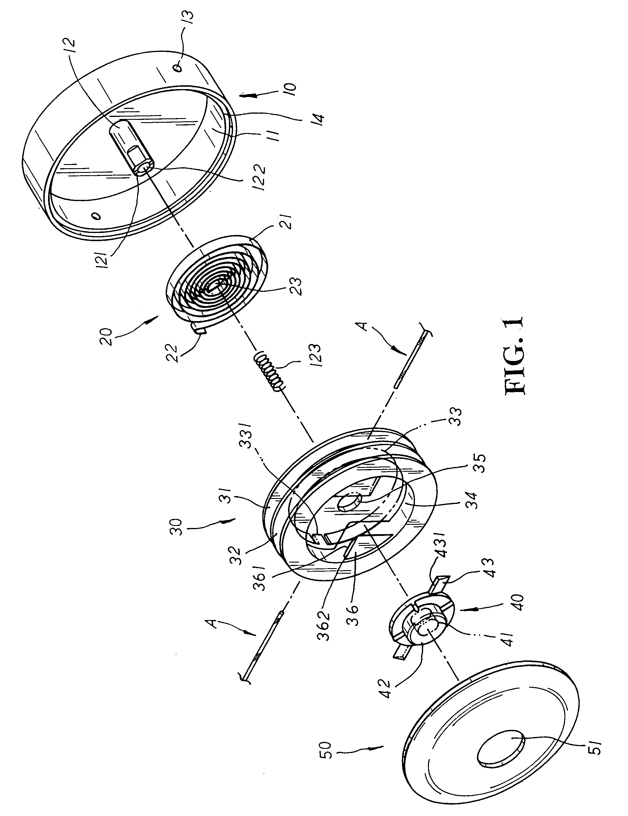
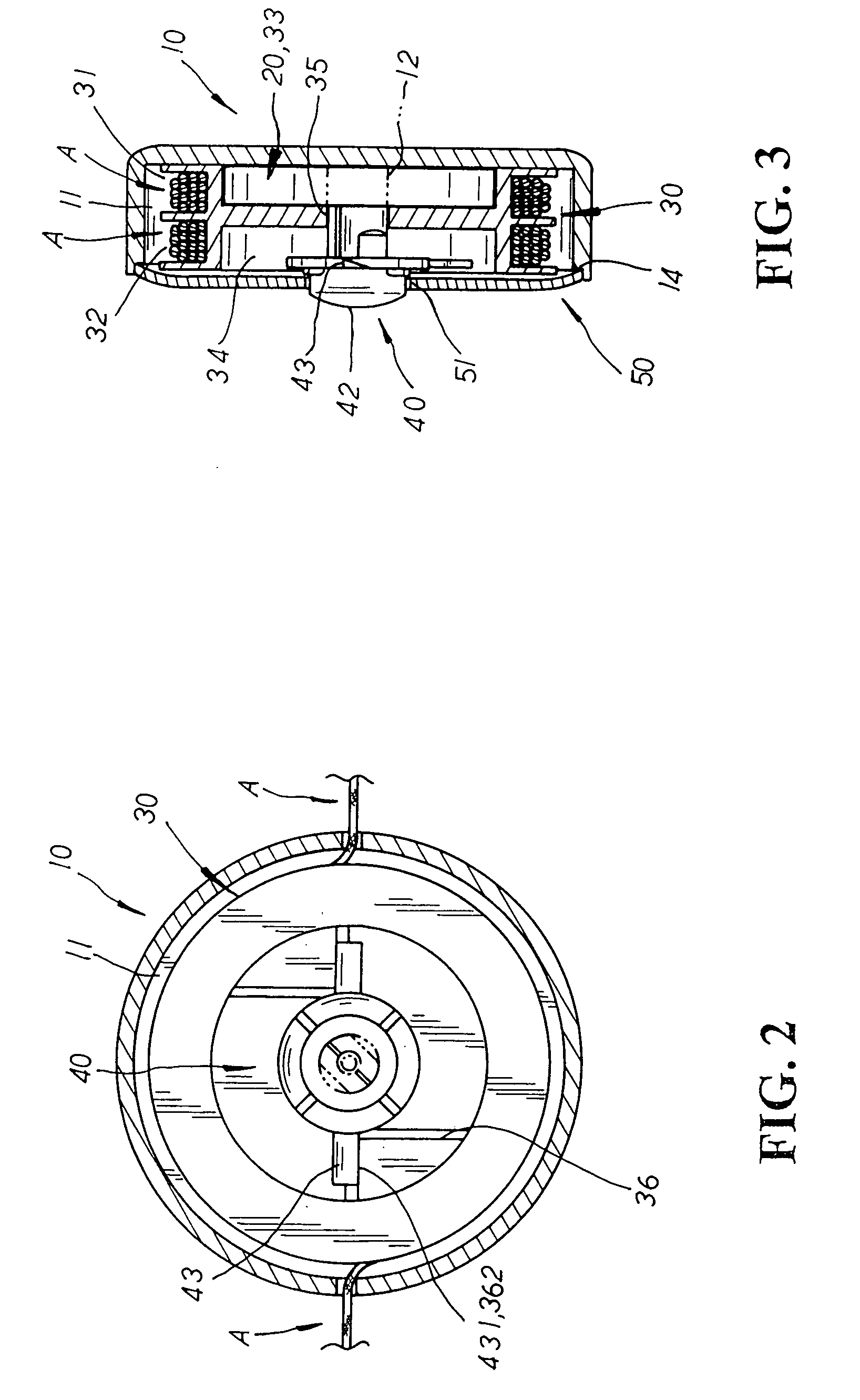
[0015] Please refer to FIG. 1. The present invention is related to a non-pull cord operated blind structure, including a retaining box 10, a recoiling spring element 20, a movable member 30, a control button 40, and a cover 50. The retaining box 10 is equipped with an engaging cavity 11 concaved at one side thereon, a locating rod 12 having level facets defined at both lateral sides thereon protruding at the center of the locating rod 12 thereof, a recess 121 of proper depth cut at the end of the locating rod 12 thereon, and a grooved hole 122 defining the center of the locating rod 12 thereof for a spring 123 to be adapted therein. Two cord passage holes 13 are disposed at both lateral walls of the retaining box 10 for a retaining cord A to be led there-through respectively, and a step-wise engaging seat 14 is disposed at the opening edge of the engaging cavity 11 thereon. The recoiling spring element 20 is made up of an elastic plate 21 wound into a spring coil with rebound elasti...


PUM


Abstract

A non-pull cord operated blind structure includes a retaining box, a recoiling spring element, a movable member, a control button, and a cover wherein the retaining box is equipped with an engaging cavity having a locating rod protruding at the center thereof to be registered with the movable member thereby, and the recoiling spring element has an inserting hook piece and a fixing piece disposed at both ends thereon to be securely attached to a recess of the locating rod thereof and an engaging hook of the movable member respectively thereby. The movable member is provided with a retaining chamber having two opposite abutting blocks with tapered guide slopes protruding at the inner periphery thereon to be abutted against tapered locating plates of the control button so as to precisely locate the movable member with retaining cords collected therein. Thus, the recoiling spring element is activated to compress tight or rebound loose by the retaining cords which is either stretched out by a lower beam pulled downwards after the control button is pushed to detach the locating plates thereof off from the abutting blocks thereof in the unfolding operation of a blind, or released from the gravity pull of the lower beam raised upwards in the folding operation thereof, facilitating an easy and fast adjustment of the non-pull cord operated blind structure.

Description

BACKGROUND OF THE INVENTION [0001] The present invention is related to a non-pull cord operated blind structure, including a retaining box, a recoiling spring element, a movable member, a control button, and a cover wherein the retaining box is equipped with an engaging cavity having a locating rod protruding at the center thereof to be registered with the movable member thereby, and the recoiling spring element has a fixing piece and an inserting hook piece disposed at both ends thereon to be attached to the locating rod and the movable member respectively thereby. The movable member is provided with a retaining chamber having two opposite abutting blocks with tapered guide slopes protruding at the inner periphery thereon to be abutted against tapered locating plates of the control button so as to precisely locate the movable member with retaining cords collected therein; whereby, the recoiling spring element is activated to compress tight or rebound loose by the retaining cords wh...

Claims


Application Information

Patent Timeline
Patent Type & Authority Applications(United States)
IPC IPC(8): E06B9/30E06B9/322E06B9/326E06B9/60E06B9/90
CPCE06B9/322E06B9/90E06B9/60E06B9/326
Inventor HSU, BEN
Owner CHING FENG BLINDS INC CO LTD
Why Eureka
Try Eureka