Combination showerhead with waterfall nozzle

Inactive Publication Date: 2005-09-22
CONAIR CORP
View PDF5 Cites 13 Cited by
  • Summary
  • Abstract
  • Description
  • Claims
  • Application Information

AI Technical Summary

Benefits of technology

[0007] It is an object of the present invention to overcome the shortcomings of the prior art mentioned above. These and other objectives are achieved by the present invention described herein. It is an object of the present invention to provide a combination faucet or shower head that includes a single or multiple nozzle shower head of a conventional type with a waterfall-type nozzle for selecti

Problems solved by technology

No existing shower or faucet head is known that combines a multiple showerhead

Method used


Image

  • Combination showerhead with waterfall nozzle
  • Combination showerhead with waterfall nozzle
  • Combination showerhead with waterfall nozzle

Examples


Embodiment Construction

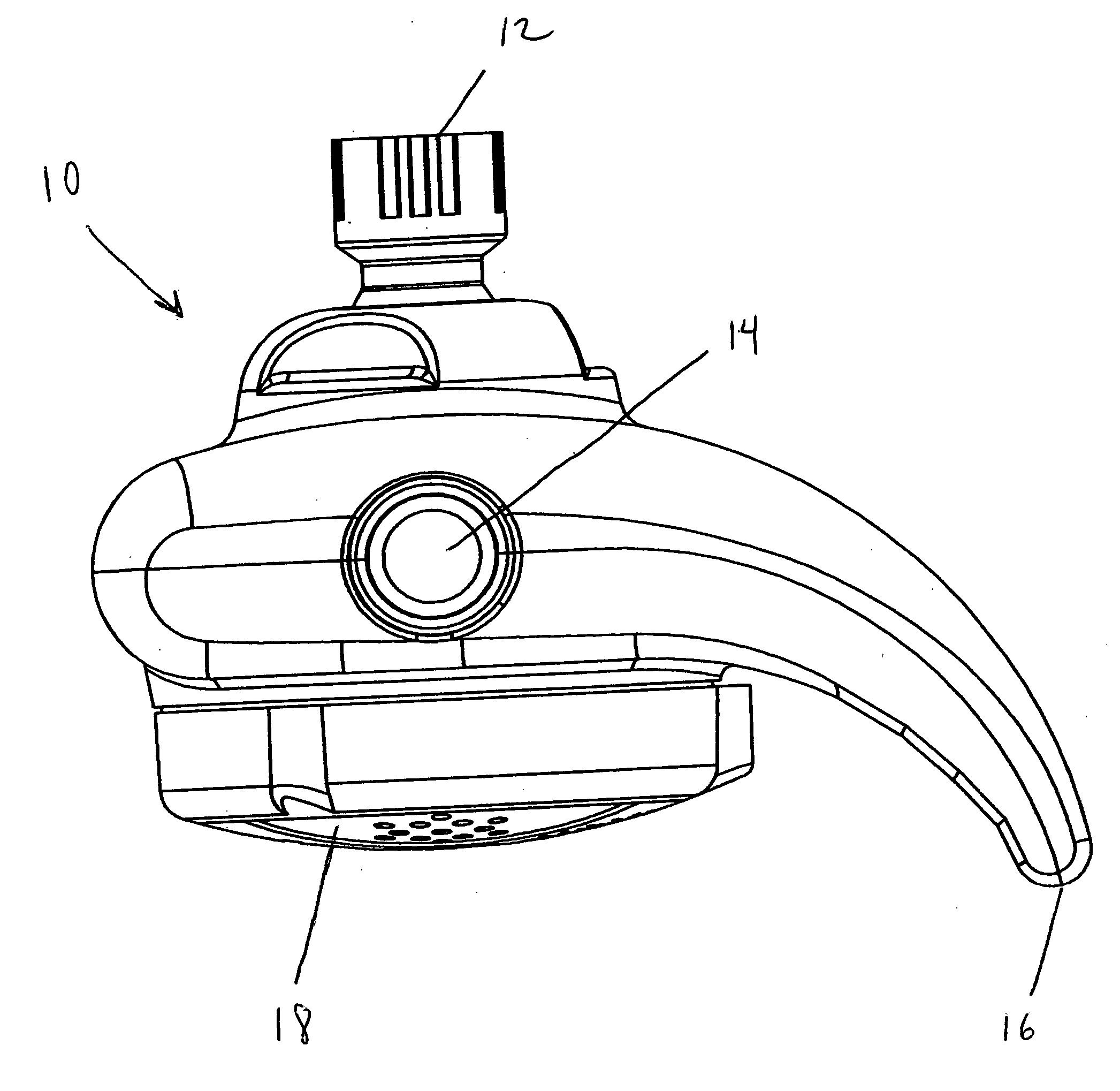
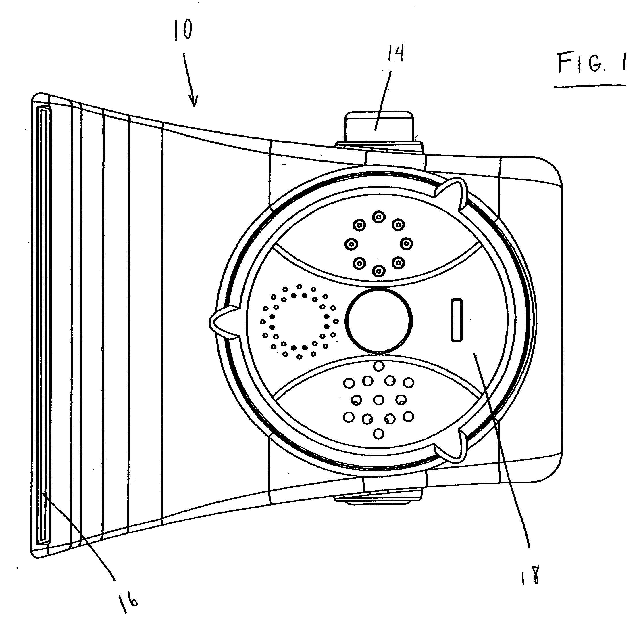
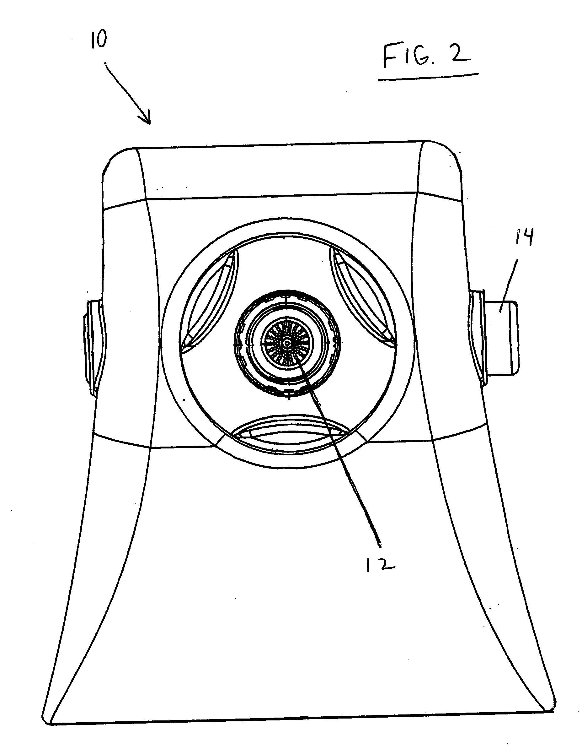
[0013] Referring to FIGS. 1-3, a shower attachment device (10) has a water inlet (12) for attachment to a typical shower faucet (not shown). A valve selector button (14) can be pushed to select either waterfall or showerhead. The valve selector button (14) is movable to selectively direct or divert water flowing from the faucet to either a waterfall nozzle (16) or conventional shower head (18). The valve selector (14) controls a conventional valve (not shown) inside the device (10).

[0014] When water is directed to the waterfall nozzle (16), which has a relatively high width-to-height ratio, a sheet or flat, continuous stream of water flows out. When water is directed to the shower head (18), typical shower spray is achieved. The shower head (18) may be a set of selectively dialed heads as shown, or a single head, each having a plurality of outlet holes as is generally known. The shower head can be rotatable, 90 degrees shift for each setting. These settings can include, for example...


PUM


Abstract

A shower attachment has a plurality of conventional shower outlet ports and a waterfall nozzle in fluid communication with a water inlet, and has a valve selector to selectively choose waterflow through the shower ports or though the waterfall nozzle.

Description

CROSS-REFERENCE TO RELATED APPLICATIONS [0001] This application claims priority to U.S. Provisional Patent Application Ser. No. 60 / 554,778 filed on Mar.20, 2004, incorporated herein by reference in its entirety.BACKGROUND OF THE INVENTION [0002] 1. Field of the Invention [0003] The present invention relates to showerheads and, more particularly, to a combination showerhead with multiple water outlets including a “waterfall” nozzle that produces a sheet-like water stream. [0004] 2. Description of Related Art [0005] A variety of showerheads exist that include multiple water outlet ports. Typically, they have various streams of conventional patterns. Certain single-outlet faucet heads, most typically used for bathtubs, have relatively high width-to-height ratios at the nozzle opening to create a sheet-like or “waterfall” effect of wide, flat, generally uninterrupted stream of water. [0006] No existing shower or faucet head is known that combines a multiple showerhead, or even a single ...

Claims


Application Information

Patent Timeline
IPC IPC(8): B05B1/00B05B1/16B05B1/18
CPCB05B1/044B05B1/16B05B1/18B05B1/1654B05B1/1636
Inventor LO, YING HOI EDDIE
Owner CONAIR CORP
Why Eureka
Try Eureka