Supercharge Your Innovation With Domain-Expert AI Agents!

Swing clamp apparatus with spring biased cam assembly

a technology of swing clamp and cam assembly, which is applied in the field of swing clamp apparatus with spring biased cam assembly, can solve the problems of “choppy” clamp operation, premature wear of conventional cam assemblies in swing clamps, and premature wear of swing clamps, so as to improve clamping speed and reduce wear

Active Publication Date: 2005-09-22
VEKTEK LLC
View PDF9 Cites 7 Cited by
  • Summary
  • Abstract
  • Description
  • Claims
  • Application Information

AI Technical Summary

Benefits of technology

"The present invention is about improving shiftable clamps, specifically swing clamps. The clamps have a hollow body with a piston and a cam assembly for controlling the movement of the piston. A spring is used to bias the ball towards the cam track, which has been found to improve clamping speed and reduce wear. The biasing spring can be a bellville spring or a small coil spring and is mounted within a recess on the clamp body. The technical effect of the invention is improved performance and durability of shiftable clamps."

Problems solved by technology

Conventional cam assemblies in swing clamps are subject to premature wear over time that interferes with the swinging operation of the clamps.
Specifically, when the cam follower ball moves in the track, it is subject to circumferential forces tending to push the ball to the sides of the groove.
The dimples and worn regions of the cam track often catch the ball during piston movement, creating a “choppy” clamp operation.
When a clamp is used in severe conditions, its cam ball may completely wear down the edges of the track, causing the ball to completely roll out of the groove.
Excessive wear on the cam grooves of a clamp can be a serious problem.
When the cam groove on a clamp become worn, the swing clamp can no longer achieve this precise and repeatable swinging movement.

Method used


Image

  • Swing clamp apparatus with spring biased cam assembly
  • Swing clamp apparatus with spring biased cam assembly
  • Swing clamp apparatus with spring biased cam assembly

Examples


Embodiment Construction

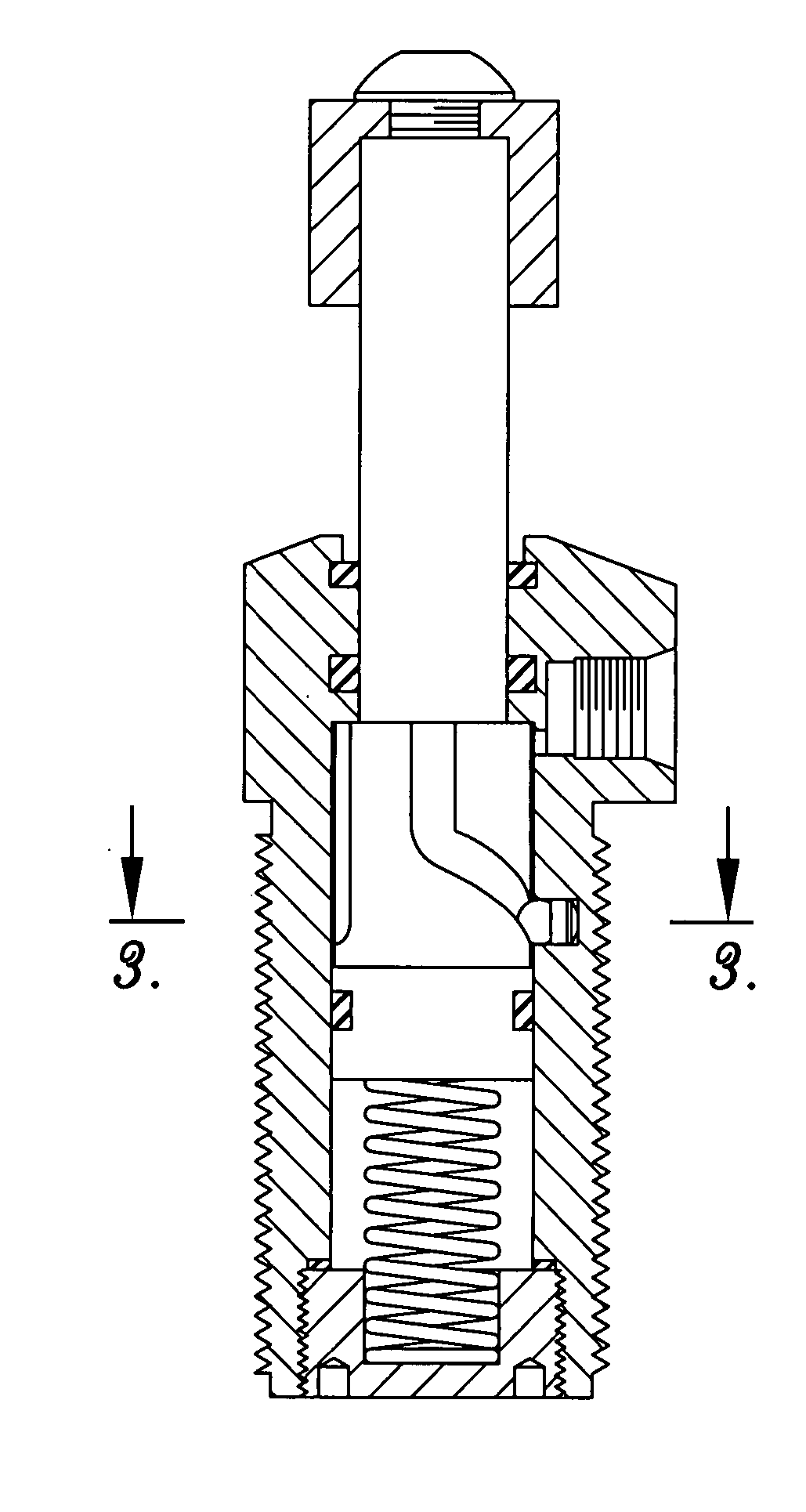
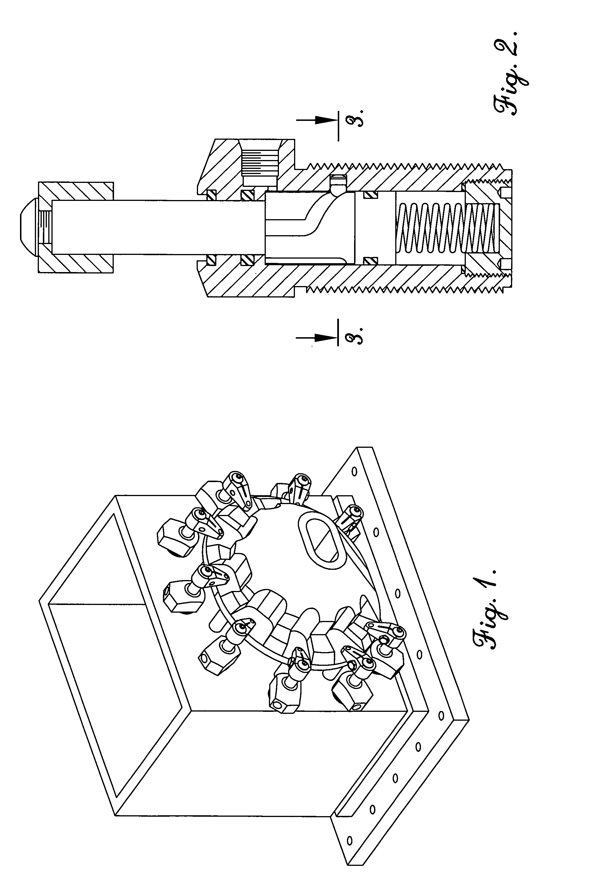
[0018] Turning now to the drawings, FIG. 1 illustrates a fixture 10 equipped with a plurality of clamps 12 adapted to releasably hold a workpiece 14 in position on the fixture 10. As illustrated, the exemplary fixture 10 includes a base 16 supporting an upright mounting box 18, the latter having a workpiece-supporting wall 20. The clamps 12 are threadably secured within threaded bores provided in wall 20 as will be described. Briefly, in operation the clamps 20 are selectively movable between the clamping position depicted in FIG. 1 to thus hold workpiece 14 in place, and a retracted, swung-away position allowing removal of the workpiece 14 after it is worked upon, and positioning of another workpiece 14 in its place.

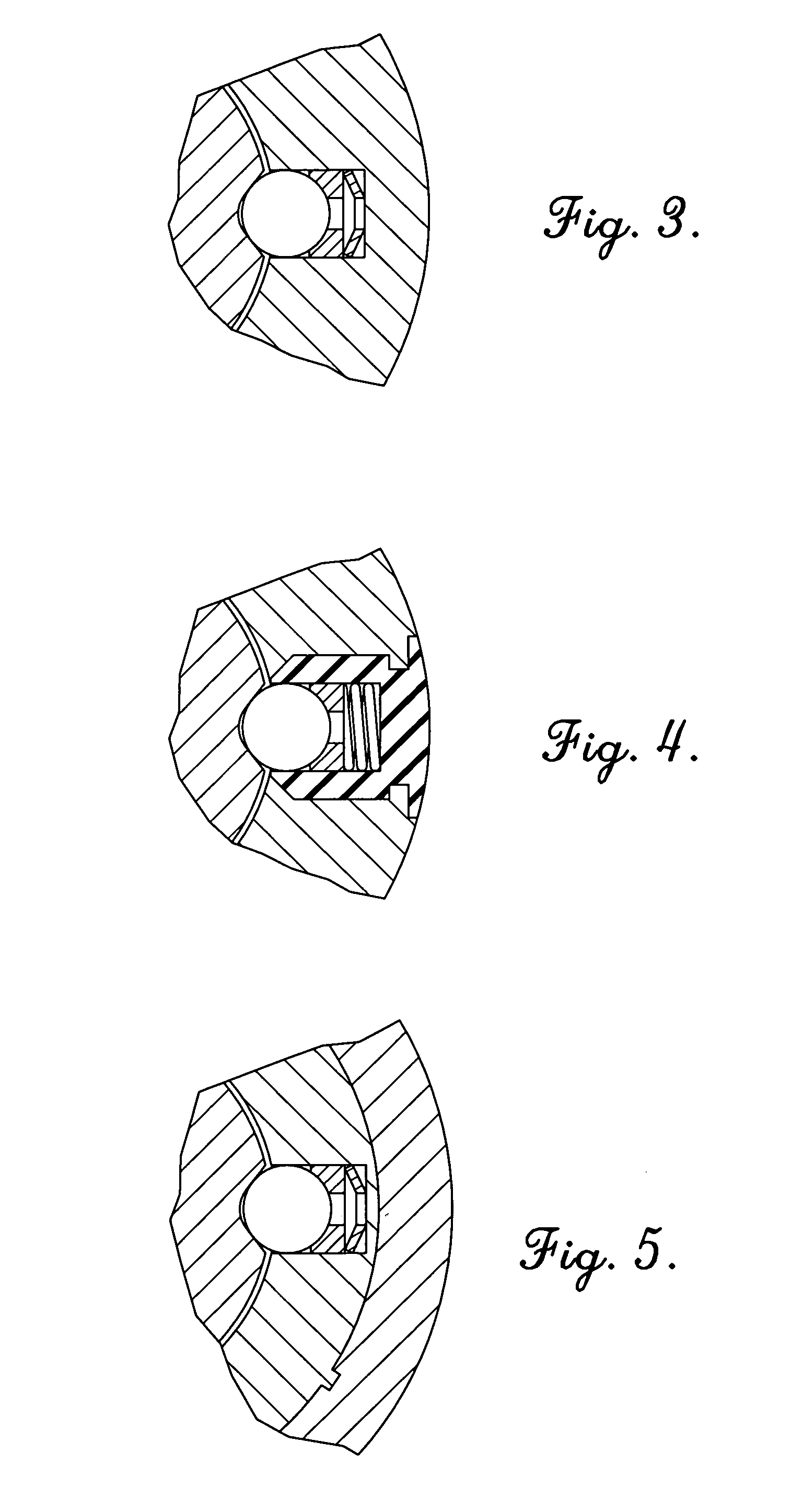
[0019] In more detail, the body 22 has an elongated segment 30 presenting an inner wall 32 as well as a threaded exterior wall 34. Each clamp 12 includes an elongated, tubular body 22 together with a piston 24 telescopically received within the body 22, and a cam assem...


PUM


Abstract

An improved shiftable clamp (12) adapted for connection to a fixture (10) is provided, wherein the clamp (12) is selectively operable to engage and hold a workpiece (14) to the fixture (10). The clamp (12) includes a tubular body (22) and a piston (24) telescopically received within the body (22). Movement of the piston (24) is guided and controlled by means of a cam assembly (26) including a cam track (64) formed in the piston (24) and an associated cam track follower ball (66) mounted on the body (22). A spring unit (74) is also provided on the body (22) and includes a spring (82, 96) serving to self-center and bias the ball (66) into the track (64). This insures that the ball (66) smoothly rotates during movement of piston (22) and reduces wear and premature clamp failure.

Description

RELATED APPLICATIONS [0001] This application is a continuation of and claims priority benefit to U.S. patent application Ser. No. 10 / 802,229, filed Mar. 17, 2004 entitled SWING CLAMP APPARATUS WITH SPRING BIASED CAM ASSEMBLY, which is hereby incorporated into the present application by reference.BACKGROUND OF THE INVENTION [0002] 1. Field of the Invention [0003] The present invention is broadly concerned with improved clamps used for clamping workpieces to fixtures, and especially so-called swing clamps which simultaneously move in axial and rotational directions to allow easy placement and removal of workpieces. More particularly, the invention is concerned with such clamps including a shiftable piston equipped with a workpiece-engaging outer head, where piston movement is guided and controlled via an internal cam assembly made up of a specially configured cam track and cam follower ball arrangement. Such cam assemblies are provided with spring units serving to bias and self-center...

Claims


Application Information

Patent Timeline
Patent Type & Authority Applications(United States)
IPC IPC(8): B25B5/06
CPCF15B15/063B25B5/062
Inventor HAUSLER, FREDERICK A. III
Owner VEKTEK LLC
Features
  • R&D
  • Intellectual Property
  • Life Sciences
  • Materials
  • Tech Scout
  • Unparalleled Data Quality
  • Higher Quality Content
  • 60% Fewer Hallucinations
Learn More