Method and device for forming horizontal stacks of printed products and securing said stacks with straps

a technology of printed products and horizontal stacks, which is applied in the field of printing product processing, can solve the problems of unstable stacks without aid, and the inability of the strapping material to place the looping channel, etc., and achieve the effects of increasing capacity, high flexibility, and more tim

Inactive Publication Date: 2005-09-22
FERAG AG
View PDF11 Cites 10 Cited by
  • Summary
  • Abstract
  • Description
  • Claims
  • Application Information

AI Technical Summary

Benefits of technology

[0010] The invention includes a method and a device for producing and strapping recumbent stacks, wherein the method and device according to the invention are to be simpler and more flexible than corresponding methods and devices according to the state of the art, and are to allow shorter time cycles, in particular for the strapping.
[0014] It is obvious that the described strapping procedure offers a very high flexibility concerning the position and number of straps to be positioned around each stack. A predetermined positioning of the strap on the stack is achieved by proportioning the corresponding motion between stack and loop. For positioning a plurality of straps, an appropriately dimensioned intermediate motion is carried out between successive strappings.
[0015] Since the loop of strapping material is able to be made ready prior to, or during, the positioning of the stack in the stacking position, and since after positioning the stack the loop only needs to be shifted a short distance (e.g. half the width of the stack), the time required for the strapping is shorter than it is possible in an device in which the looping channel is not brought into a functional condition to enable the loop to be made ready until after the positioning of the stack. Therefore, according to the invention more time is available for moving the stack into the strapping position and therefore, the capacity can be increased, and / or shorter stacks can be produced.
[0016] It shows that the isolation of discreet stacks from the continuously growing stack, the positioning of the endplates at the ends of the isolated stacks, and the taking over of the stacks by the compression jaws are particularly easily achieved if the compression jaws reach into the stack area above the conveying surface from one side only. For this purpose, two support elements are advantageously employed, which can be brought into the stack area from below (raised, active position) and retracted from the stack area (lowered, inactive position) and can be cyclically moved back and forth, parallel to the stacking direction. The design of the support elements is such that they can be simultaneously positioned in the same position of the stack area, i.e. one support element can be slotted into the other one.

Problems solved by technology

This means that such stacks are unstable without aid, even in an upright position.
This means that the loop of the strapping material cannot be placed in the looping channel until the stack is positioned in the strapping position and the vertical channel component has been repositioned in its active position above the conveying surface.

Method used


Image

  • Method and device for forming horizontal stacks of printed products and securing said stacks with straps
  • Method and device for forming horizontal stacks of printed products and securing said stacks with straps
  • Method and device for forming horizontal stacks of printed products and securing said stacks with straps

Examples


Embodiment Construction

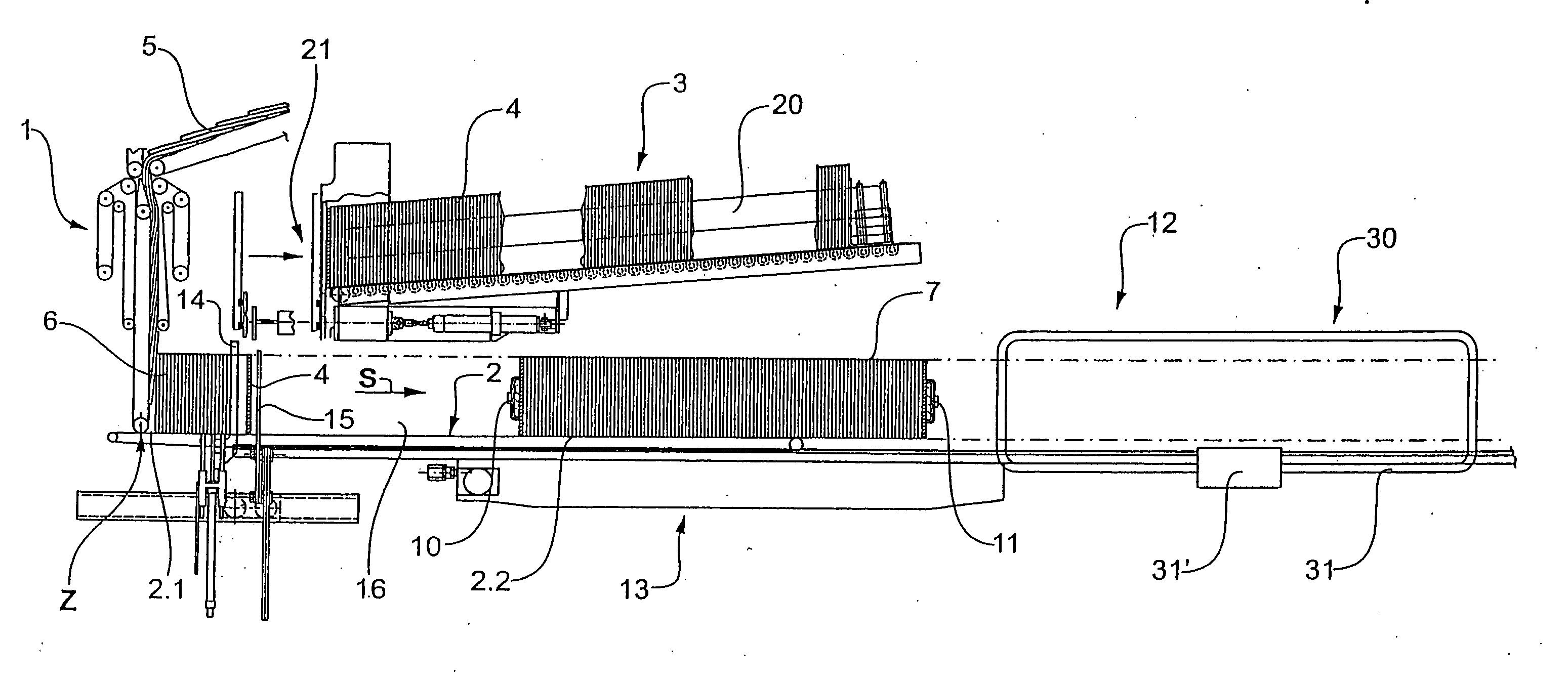
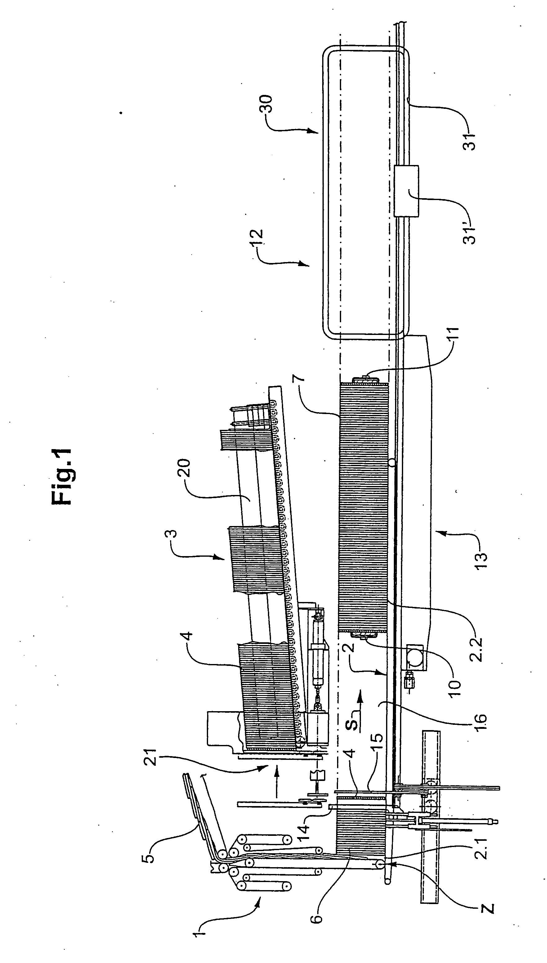
[0024]FIG. 1 is a side view of an exemplary embodiment of the device according to the invention. The device comprises in a generally known manner a supply means 1 and a conveying surface 2, as well as a means 3 for positioning the endplates 4. The supply means 1 comprises e.g. a pair of conveyor belts, driven counter-revolvingly, between which an imbricated stream 5 is conveyed from above on to the conveying surface 2 (supply point Z). The conveying surface 2 is e.g. a conveyor belt moving away from the supply point (stacking direction S) or a plurality of conveyor belts operating in parallel and / or in series. It is advantageous to provide a first conveyor belt 2.1 adjacent the supply point Z, which first conveyor belt is operated continuously with approximately the speed of the stack growth and a second conveyor belt 2.2 which is operated with a cyclically variable speed.

[0025] The supplied products line up on the conveying surface 2 to form a continuously growing stack 6, which e...


PUM

PropertyMeasurementUnit
lengthaaaaaaaaaa
lengthaaaaaaaaaa
areaaaaaaaaaaa

Abstract

Recumbent stacks of printed products are produced and strapped by supplying the printed products from above onto a conveying surface (2) where they are lined up in an upright position forming a continuously growing stack (6), separating discreet stacks (7) from the growing stack, stabilizing the discreet stacks with endplates (4), and conveying the stabilized stacks to a strapping position (12), in which a loop of strapping material is tightened around the stack (7). For conveying and strapping, the isolated stack (7) is gripped between two compression jaws (10, 11) that extend into the stack area (16) from a first side. In the strapping position (12), a strapping device (30) is situated on the side opposite the stack area (16). For strapping, at least part of the strapping device is moved horizontally in relation to the stack, and transverse to the stacking direction (S), thereby placing a loop of the strapping material around the stack. The loop is then tightened and closed around the stack and the compression jaws (10, 11) and the strapped stack is separated from the compression jaws by moving the stack (7) and the compression jaws (10, 11) relative to each other, horizontally and transverse to the stacking direction.

Description

BACKGROUND OF THE INVENTION [0001] 1. Field of the Invention [0002] The invention is situated in the area of the further processing of printed products and concerns a method and device in accordance with the generic parts of the corresponding, independent claims. Method and device serve the production and strapping of recumbent stacks of printed products. [0003] 2. Description of the Related Art [0004] In the printing industry, intermediate and part products, such as individual sections of newspapers and periodicals being printed prior to other sections, signatures to be made into books, or single sheets, prospectuses, small brochures, part sheets, etc. to be inserted into newspapers or periodicals as supplements or as collated parts, require intermediate storage between production and further processing and therefore must be transported within the company or, if necessary, from one company to another. For such intermediate storage and transportation it has long proven advantageous ...

Claims


Application Information

Patent Timeline
Patent Type & Authority Applications(United States)
IPC IPC(8): B65B27/08B65H33/02
CPCB65B27/08B65H31/3072B65H33/02B65H2301/4263B65H2301/4223B65H2301/42242B65H2301/42265B65H2301/42146
Inventor GOSSLINGHOFF, REINHARD
Owner FERAG AG
Why Eureka
Try Eureka