Self-calibrating oscillator system

a self-calibration and oscillator technology, applied in the direction of oscillator starters, automatic control of pulses, oscillator generators, etc., can solve the problems of preventing the vco from starting up properly, counteracting the efforts to reduce the noise at the output of a vco, and causing oscillation to begin

Active Publication Date: 2005-09-22
NXP USA INC
View PDF5 Cites 31 Cited by
  • Summary
  • Abstract
  • Description
  • Claims
  • Application Information

AI Technical Summary

Problems solved by technology

However, the reduction of current drain, for example, to extend battery life of a device, generally counteracts efforts to reduce noise at the output of a VCO.
In addition, the desirable VCO qualities of guaranteed start-up and wide tuning bandwidth also create design trade-off problems with noise minimization.
However this practice can prevent the VCO from starting up properly when power is initially applied.
A large supply voltage ensures that the oscillator will start in a predictable manner, while too small of a supply voltage may not provide enough energy to cause oscillation to begin.
However, large supply voltages consume more power, which requires larger on-chip devices that increase parasitic capacitance and current drain, while reducing the Q and adversely affecting the tuned bandwidth of a system.
This feedback signal however, is itself a source of additional noise and can require significant overhead to support applications with different output requirements.

Method used


Image

  • Self-calibrating oscillator system
  • Self-calibrating oscillator system
  • Self-calibrating oscillator system

Examples


Embodiment Construction

)

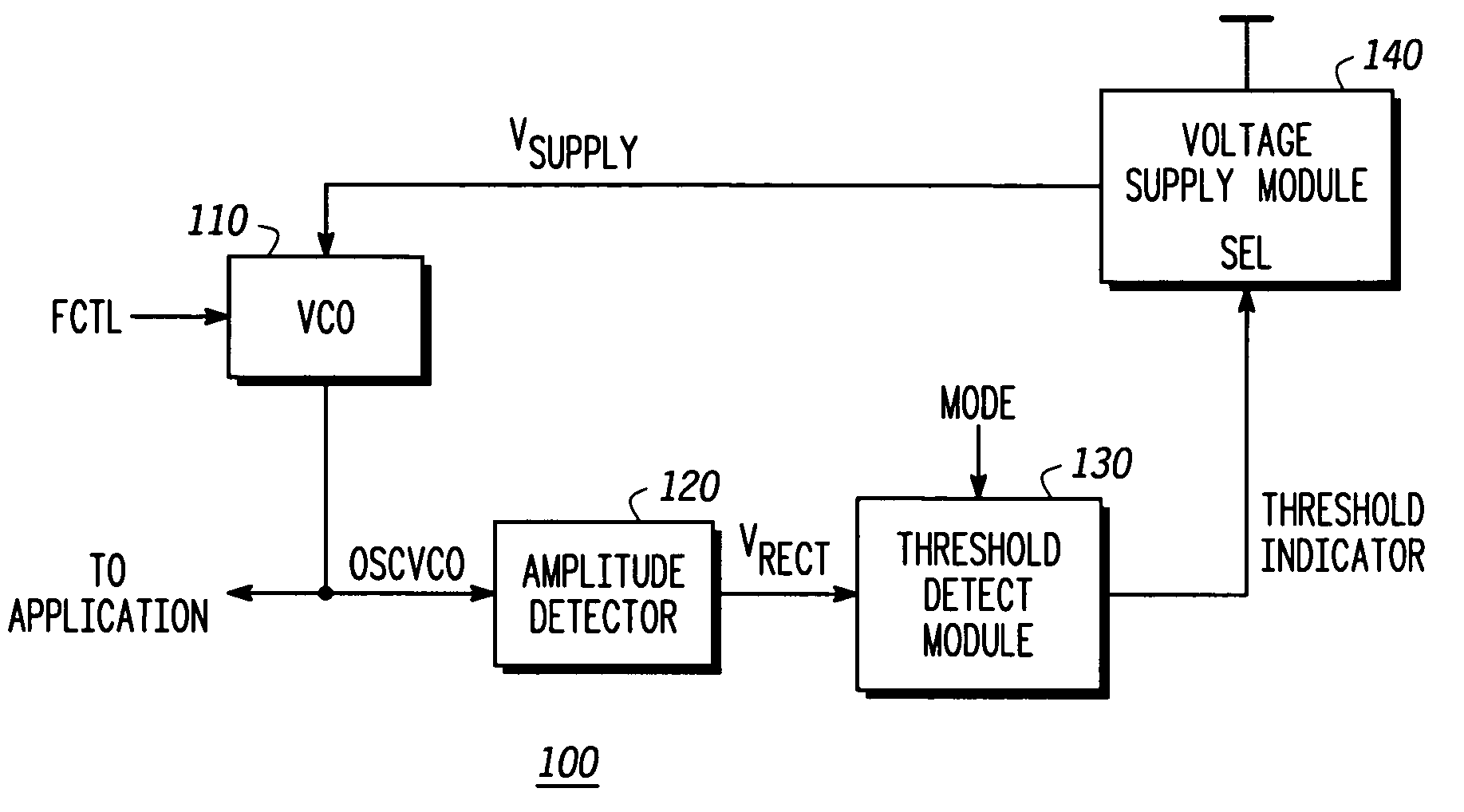
[0015] The present disclosure is generally directed towards systems and methods to monitor the output of an oscillator to determine if the oscillator is in a specific operating condition such as a start-up mode. If so, a selection is made within the system to supply a first supply voltage to the oscillator. Otherwise an alternate supply voltage is selected. The present disclosure is better understood with respect to FIGS. 1-6.

[0016]FIG. 1 illustrates in block diagram form a voltage-controlled oscillator (VCO) module system 100 in accordance with a specific embodiment of the present disclosure. The VCO system 100 includes a VCO 110, an amplitude detector module 120, a threshold detect module 130, and a voltage supply module 140. VCO module 110 has an input to receive a frequency control signal called FCTL and an input to receive a voltage supply called VSUPPLY, and an output called OSCVCO. It will be appreciated that a VCO is illustrated as a specific embodiment and that other sign...


PUM


Abstract

A system comprising a voltage controlled oscillator is disclosed. The voltage controlled oscillator includes a single input, a power input, and an oscillation input. The oscillation input is coupled to a amplitude detection device, which in turn provides an indication of an amplitude of the output of the VCO to a threshold detect module. Based upon the threshold detected at the threshold detect module, a threshold indicator is provided to a voltage supply module. The voltage supply powering the voltage controlled oscillator is varied, based upon a value of the threshold indicator.

Description

BACKGROUND [0001] 1. Field of the Disclosure [0002] The present disclosure is generally related to semiconductor devices and more particularly to signal-controlled oscillators. [0003] 2. Description of the Related Art [0004] Radio communication devices, such as cellular telephones, usually include a voltage-controlled oscillator (VCO) as part of their circuitry. To produce the highest quality output signal, noise in the output signal of the VCO should be minimized. However, the reduction of current drain, for example, to extend battery life of a device, generally counteracts efforts to reduce noise at the output of a VCO. In addition, the desirable VCO qualities of guaranteed start-up and wide tuning bandwidth also create design trade-off problems with noise minimization. One method of reducing current drain is for the supply voltage to the VCO to be just large enough to support a specific application. However this practice can prevent the VCO from starting up properly when power is...

Claims


Application Information

Patent Timeline
Patent Type & Authority Applications(United States)
IPC IPC(8): H03L3/00H03L5/00H03L7/00H03L7/06
CPCH03L3/00H03L7/06H03L5/00
Inventor GODAMBE, NIHAL J.KEHLER, WALTER H.
Owner NXP USA INC
Why Eureka
Try Eureka