
Auxiliary eyeglasses with two aligned springs for biasing two lens units to move relative to each other

a technology of auxiliary eyeglasses and springs, which is applied in the field of pair of auxiliary eyeglasses, can solve the problems of affecting the appearance of the second conventional auxiliary eyeglasses, the structure of the bridge, and the wearer's health, so as to reduce the size of the bridge and not mar the appearance of the auxiliary eyeglasses

Inactive Publication Date: 2005-09-22
EVERGREAT OPTICAL IND
View PDF6 Cites 8 Cited by
  • Summary
  • Abstract
  • Description
  • Claims
  • Application Information

AI Technical Summary

Benefits of technology

"The invention is a pair of auxiliary eyeglasses that can be added to existing glasses to improve their performance. The auxiliary eyeglasses have two lens units, two retaining units that attach to the existing glasses, and a rigid connecting tube that connects the lens units. The connecting tube has two non-circular holes that are engaged by two movable rods that are fixed to the lens units. The rods have flanges that fit into the non-circular holes, preventing rotation. The auxiliary eyeglasses also have two coiled compression springs that bias the rods together, clamping the existing glasses between the retaining units. The small size of the connecting tube and the concealment of the springs make the auxiliary eyeglasses appear to be a simple pair of glasses. No slot is formed in the connecting tube to prevent any debris from entering."

Problems solved by technology

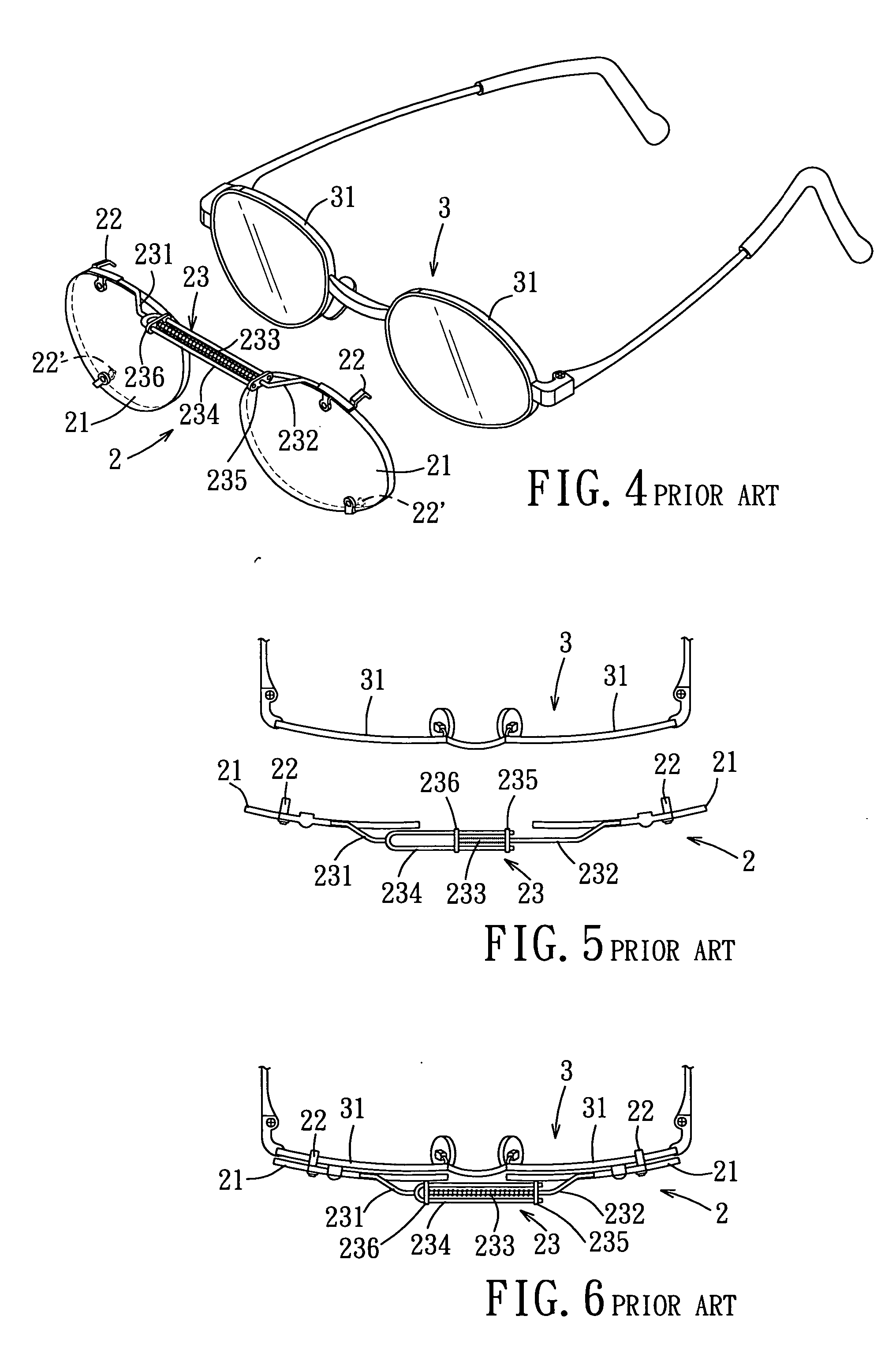
The second conventional auxiliary eyeglasses 2 are disadvantageous in that the bridge 23 has a relatively large size.
Furthermore, the structure of the bridge 3 will affect adversely the appearance of the second conventional auxiliary eyeglasses 2.
However, small external articles may enter into the cylindrical enclosure through the slot to thereby affect the biasing function of the coiled spring.
In this case, the hair of the wearer may be clamped between the cylindrical enclosure and the coiled spring, thereby hurting the wearer.

Method used


Image

  • Auxiliary eyeglasses with two aligned springs for biasing two lens units to move relative to each other
  • Auxiliary eyeglasses with two aligned springs for biasing two lens units to move relative to each other
  • Auxiliary eyeglasses with two aligned springs for biasing two lens units to move relative to each other

Examples


Embodiment Construction

[0031] Before the present invention is described in greater detail in connection with the preferred embodiments, it should be noted that similar elements and structures are designated by like reference numerals throughout the entire disclosure.

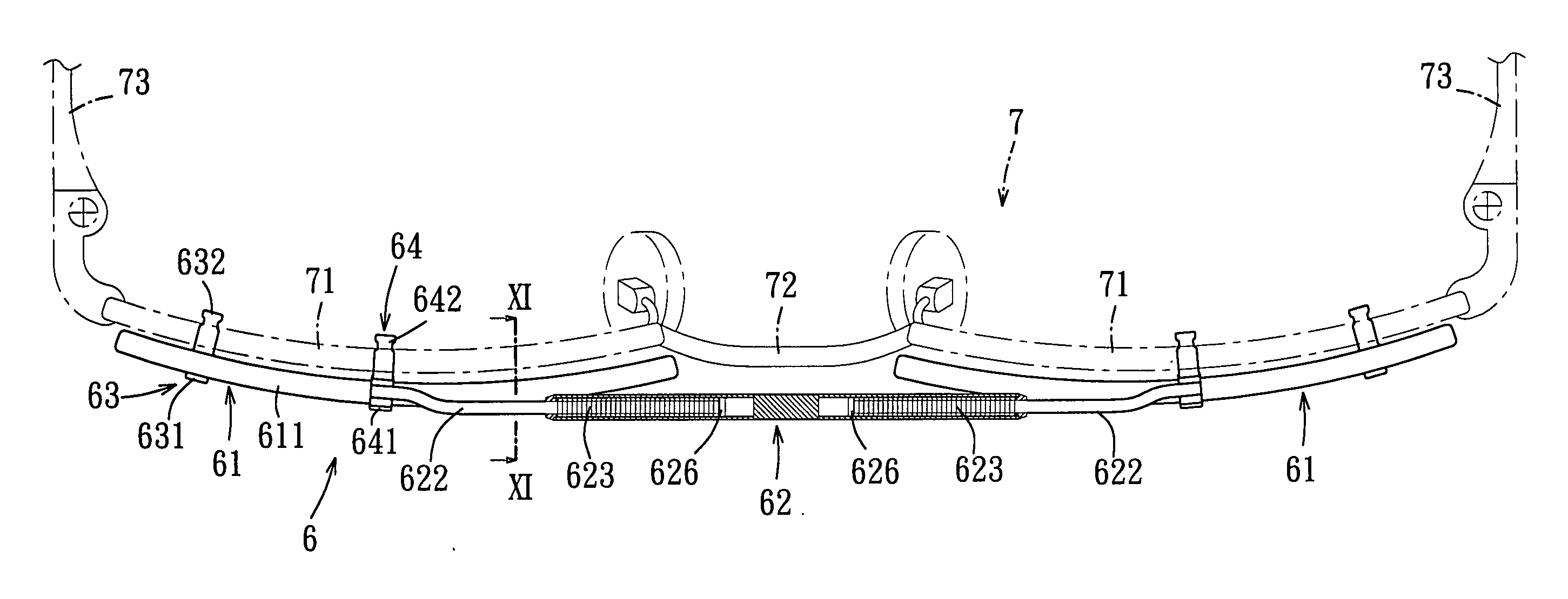
[0032] Referring to FIG. 7, the first preferred embodiment of a pair of frameless auxiliary eyeglasses 6 according to this invention is shown to include two lens units 61, a bridge 62, and two retaining units, each of which has a lower retaining member 63 and an upper retaining member 64. The auxiliary eyeglasses 6 are adapted to be disposed on and in front of a pair of primary eyeglasses 7 (see FIG. 9) that includes two lens units 71, a bridge 72, and two temples 73. Each of the lens units 61 includes a lens 611. The lower and upper retaining members 63, 64 of each of the retaining units are connected to the corresponding lens unit 61 in a known manner, and are adapted to be attached to the corresponding lens unit 71 of the primary eyeglasse...


PUM


Abstract

A pair of auxiliary eyeglasses is attached to a pair of primary eyeglasses, and has a bridge including a rigid connecting tube that is disposed between two lens units. Two movable rods are connected respectively to the lens units, extend respectively through two open ends of the connecting tube, are movable within the connecting tube, and engage respectively and fittingly the non-circular holes in the inward flanges so as to prevent rotation of the movable rods relative to the connecting tube. The auxiliary eyeglasses further include two coiled compression springs, each of which is disposed between the outward flange of a respective one of the movable rods and a respective one of the inward flanges of the connecting tube so as to bias the movable rods to move toward each other.

Description

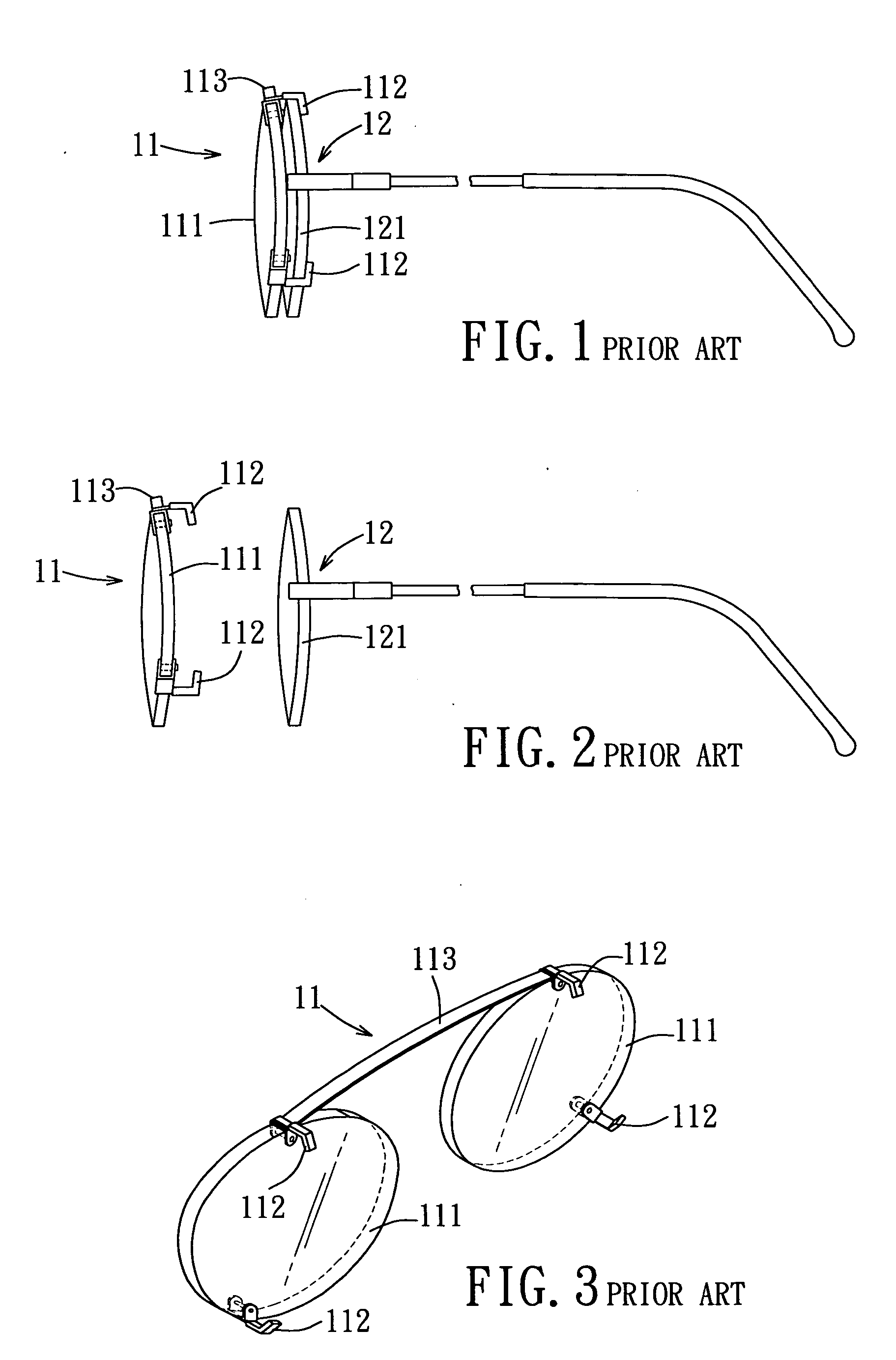
CROSS-REFERENCE TO RELATED APPLICATION [0001] This application claims priority of Taiwanese Application No. 093204111, filed on Mar. 18, 2004. BACKGROUND OF THE INVENTION [0002] 1. Field of the Invention [0003] This invention relates to a pair of auxiliary eyeglasses disposed on and in front of a pair of primary eyeglasses, and more particularly to a pair of auxiliary eyeglasses that includes two aligned springs for biasing two lens units to move toward each other. [0004] 2. Description of the Related Art [0005] Referring to FIGS. 1, 2, and 3, a pair of first conventional auxiliary eyeglass 11 is shown to include two lens units 111, four retaining hooks 112, and a bridge 113. The lens units 111 are retained on a lens unit 121 of a pair of primary eyeglasses 12 by the retaining hooks 112. The bridge 113 has two ends that are connected respectively and fixedly to the lens units 111. Because the length of the bridge 113 is fixed, the first conventional auxiliary glasses 11 is not suita...

Claims


Application Information

Patent Timeline
Patent Type & Authority Applications(United States)
IPC IPC(8): G02C5/04G02C9/00
CPCG02C5/045G02C9/00G02C5/08G02C9/04
Inventor CHOW, SHENG-TANG
Owner EVERGREAT OPTICAL IND
Learn More