
Recording apparatus

a recording apparatus and a technology for ejecting sheets, applied in electrical apparatus, printing, pictoral communication, etc., can solve problems such as difficulty in ejecting sheets from the back side and ejecting them to the front side, uneven recording, and rise of trailing edge of sheets, so as to achieve reliable execution

Inactive Publication Date: 2005-09-22
SEIKO EPSON CORP
View PDF15 Cites 8 Cited by
  • Summary
  • Abstract
  • Description
  • Claims
  • Application Information

AI Technical Summary

Benefits of technology

[0006] It is therefore an object of the present invention to provide a recording apparatus capable of maintaining highly accurate recording as well as a like liquid ejection apparatus.
[0011] With this configuration, particularly in ejecting a sheet or paper whose recording face is prone to be scratched, the recording face can be prevented from being scratched by separating the press member, whereby the recording accuracy can be kept high.
[0013] With this configuration, an optimum ejecting condition can be set in accordance with the property of the recording medium. In a case where it is configured an automatic switching operation can be performed, the scratching on the recording face due to the wrong switching operation of the user can be reliably avoided.
[0015] With this configuration, projecting the supporting member particularly when a trailing end of the recording medium becomes a free end, the trailing end is supported so as to prevent from being lifted up. Accordingly, it is possible to execute a recording operation with high accuracy and the termination of the recording member can be avoided.
[0018] With this configuration, the mechanism of the switcher can be made simple so that the switching operation can be reliably executed.
[0027] With the above configurations, it is possible to provide a liquid ejection apparatus having the respective advantages described the above.

Problems solved by technology

In such large-size ink jet printers, a sheet is supplied from and ejected to the front side for the following reason: unlike in small-size ink jet printers, it is difficult to supply a sheet from the back side and eject it to the front side because relatively heavy sheets need to be handled.
Further, where the above ink jet printer performs recording on a portion of a sheet close to its trailing edge, the trailing edge of the sheet may rise though the recording is going on because the trailing edge of the sheet is no longer held between the sheet feeding roller and an associated follower roller.
This may result in a problem that recording unevenness occurs because the interval between the sheet and the recording head becomes non-uniform to vary the flying distance of ink droplets or the sheet touches the recording head and is thereby stained.

Method used


Image

  • Recording apparatus
  • Recording apparatus
  • Recording apparatus

Examples


Embodiment Construction

[0060] An embodiment of the present invention will be hereinafter described in detail with reference to the accompanying drawings.

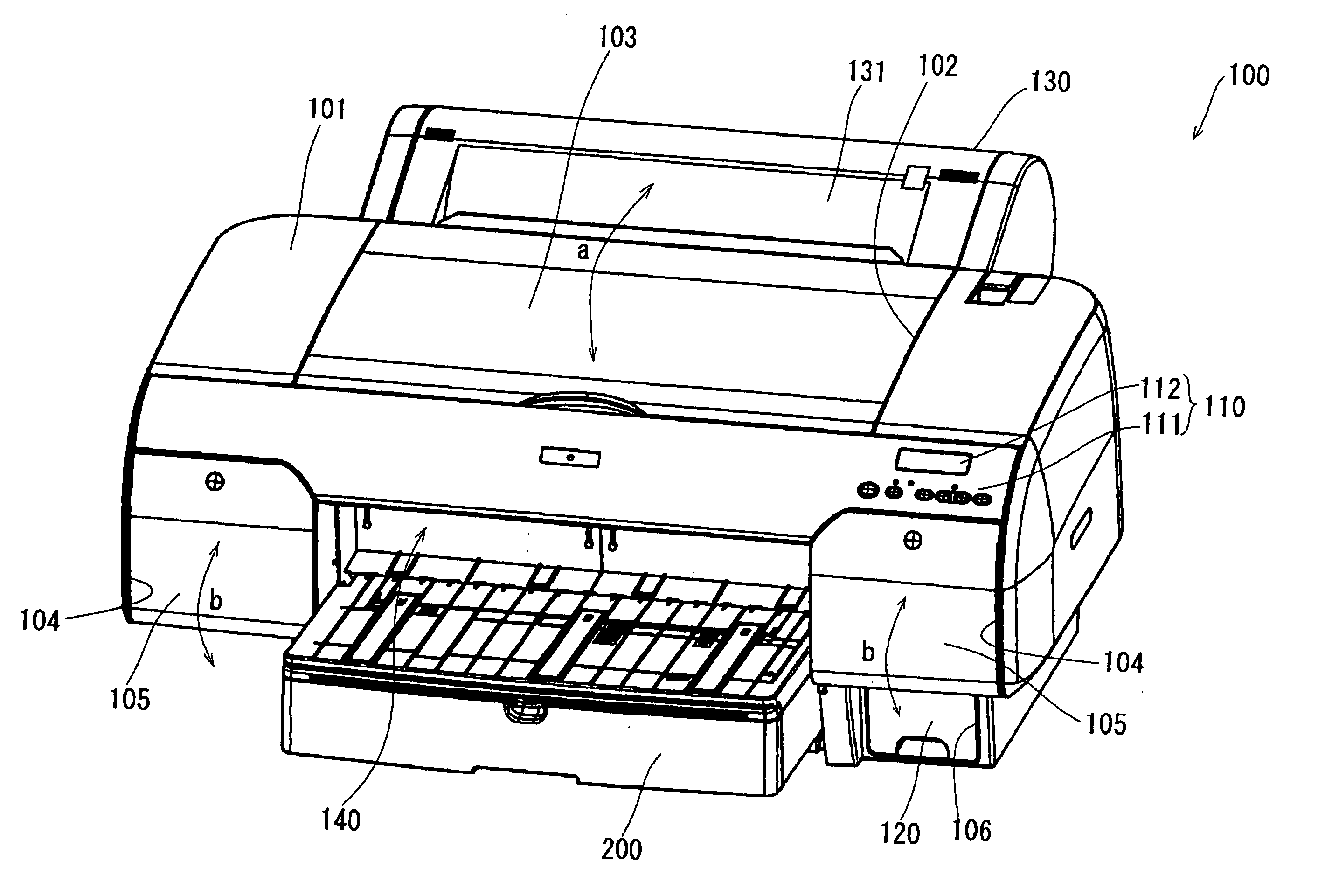
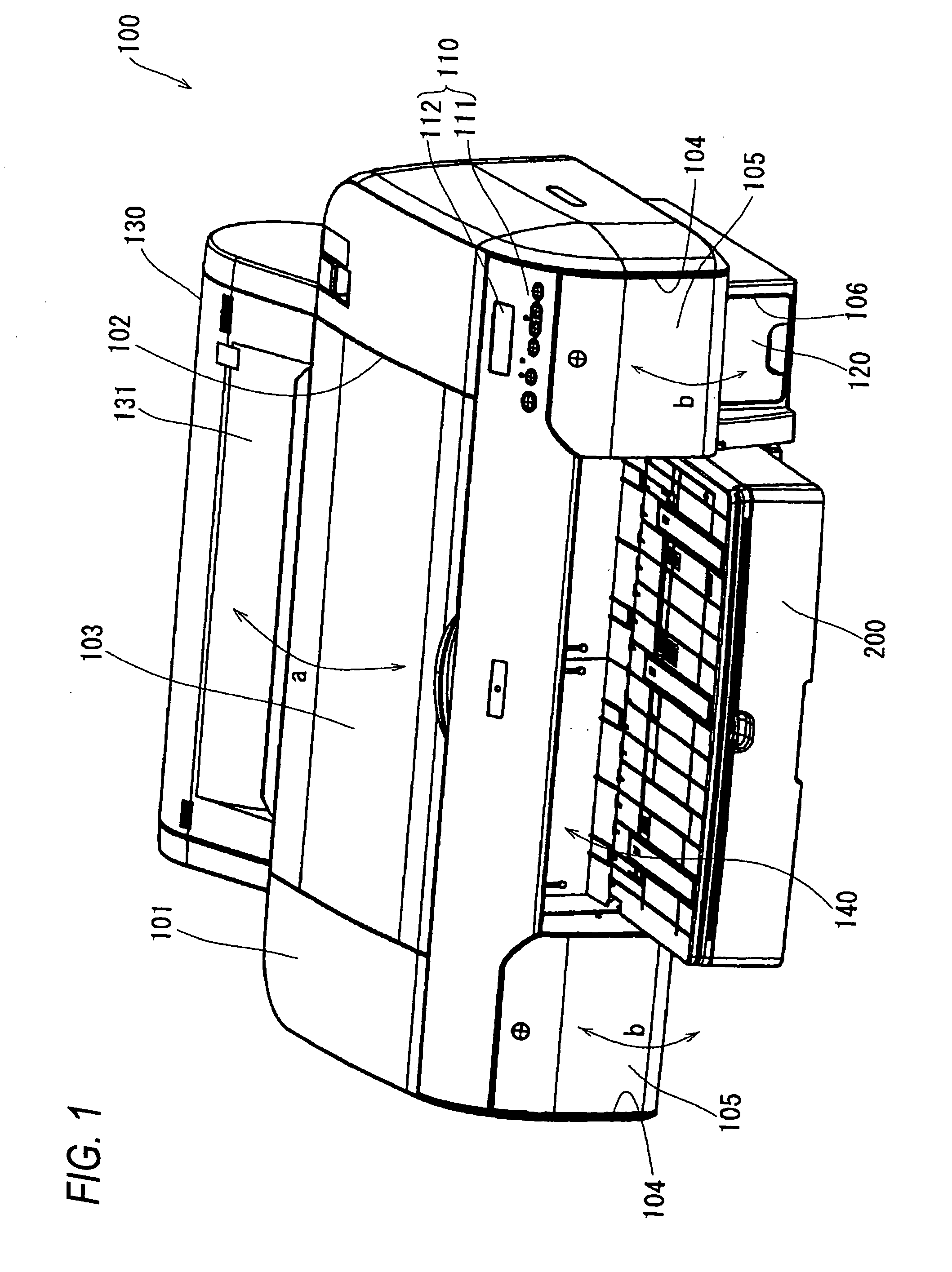
[0061] As shown in FIG. 1, an ink jet printer (recording apparatus) 100 according to an embodiment of the invention is a large-size, desk-top printer capable of recording on what is called cut sheets of a relatively large size such as the A4 to A2 size of the JIS standard and an equivalent roll of paper. The inside of the ink jet printer 100 is entirely covered with an housing 101 that generally assumes a rectangular parallelepiped shape that is long in the width direction.

[0062] The top face of the housing 101 is formed with a rectangular window 102, which is covered with a transparent or semi-transparent window cover 103. The window cover 103 is attached so as to be rotatable in directions indicated by arrow a in FIG. 1 about a rotation axis that is located on the rear side. A user can perform maintenance work or the like on the internal mechanisms th...


PUM


Abstract

A recording section is configured to perform a recording operation with respect to a recording medium. An ejector is configured to eject the recording medium transported from the recording section to the outside of the recording apparatus. The ejector is provided with a plurality of press members. A switcher selectively causes none or one of the press members to abut against the recording medium.

Description

BACKGROUND OF THE INVENTION [0001] The present invention relates to a recording apparatus that performs a recording operation by supplying a recording medium to a recording section and ejects the recording medium from an ejecting section, as well as to a like liquid ejection apparatus. [0002] Among large-size recording apparatus capable of recording on up to a sheet (recording medium) of a relatively large size such as the A4 to A2 size of the JIS standard are ink jet printers. In such large-size ink jet printers, a sheet is supplied from and ejected to the front side for the following reason: unlike in small-size ink jet printers, it is difficult to supply a sheet from the back side and eject it to the front side because relatively heavy sheets need to be handled. [0003] An ink jet printer is known in which a sheet supply tray and a sheet ejection tray are disposed on the front side. A sheet that is accommodated in the sheet supply tray is taken out by a sheet supply roller and the...

Claims


Application Information

Patent Timeline
Patent Type & Authority Applications(United States)
IPC IPC(8): B41J13/10
CPCB41J13/106
Inventor MIYAZAKI, KENICHIFUJIOKA, KAZUYUKI
Owner SEIKO EPSON CORP
Learn More