Machine tool

Inactive Publication Date: 2014-10-30
MURATA MASCH LTD
View PDF16 Cites 19 Cited by
  • Summary
  • Abstract
  • Description
  • Claims
  • Application Information

AI Technical Summary

Benefits of technology

The present invention provides a machining equipment that reduces vibrations from outside and inside the equipment, which prevents them from affecting the processing performed on a workpiece. This is achieved by using a machine tool with a machine bed, a processing machine, a shroud, and a shroud support member that supports the shroud in a non-contact fashion with respect to the machine bed. A loader that holds the workpiece can also be used with the machine tool, and the shroud support member also supports the rail, preventing vibrations from affecting the processing machine. If multiple processing machines are installed on separate machine beds, vibrations generated by one machine will not be transmitted to other machines, preventing adverse effects on their processing.

Problems solved by technology

Also, if the travelling rail 22 for the loader is installed on the shroud support member 6, vibrations resulting from the travel of the loader may be transmitted to the processing equipment and, hence, the processing performed by each of the processing equipment may be adversely affected.
However, in order to install the stands 60 on the floor surface F in a stabilized fashion, an anchor plate 61a for each of the stands 60 provided at a site at which the corresponding stand 60 is fixed to the floor surface F, need be increased in size and, therefore, there arises a problem that the space for installation of the machine tool as a whole tends to increase.

Method used


Image

  • Machine tool
  • Machine tool
  • Machine tool

Examples


Embodiment Construction

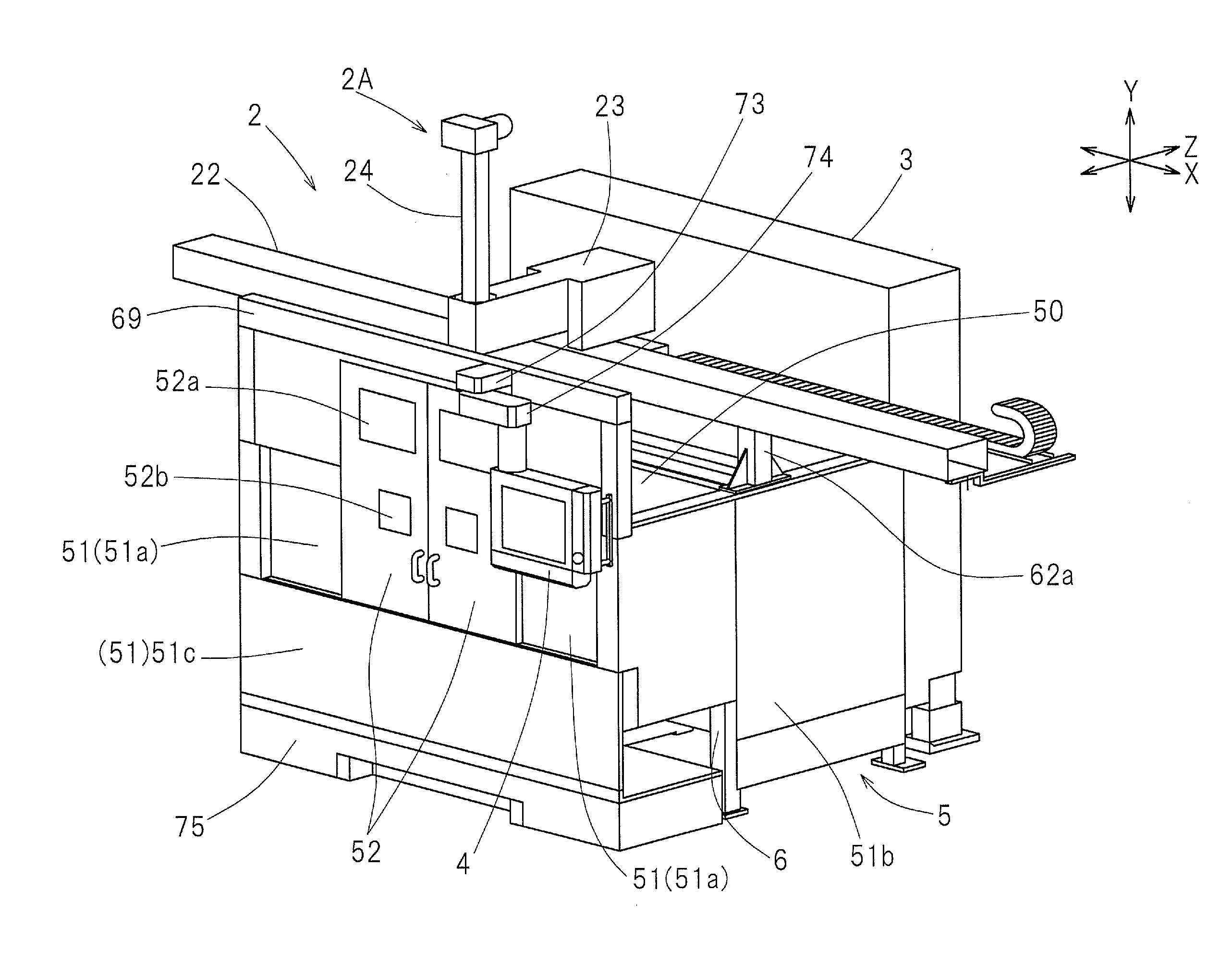
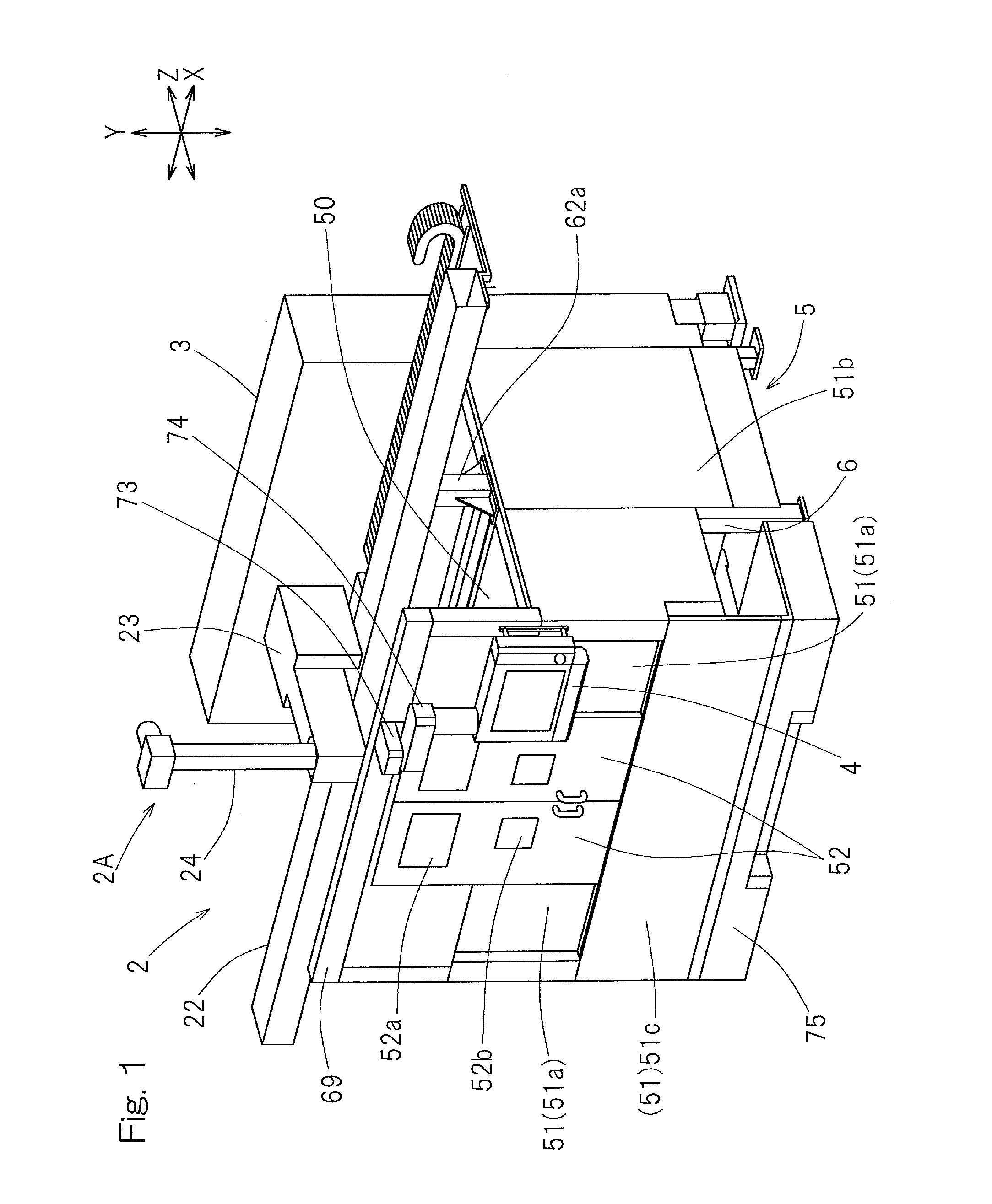
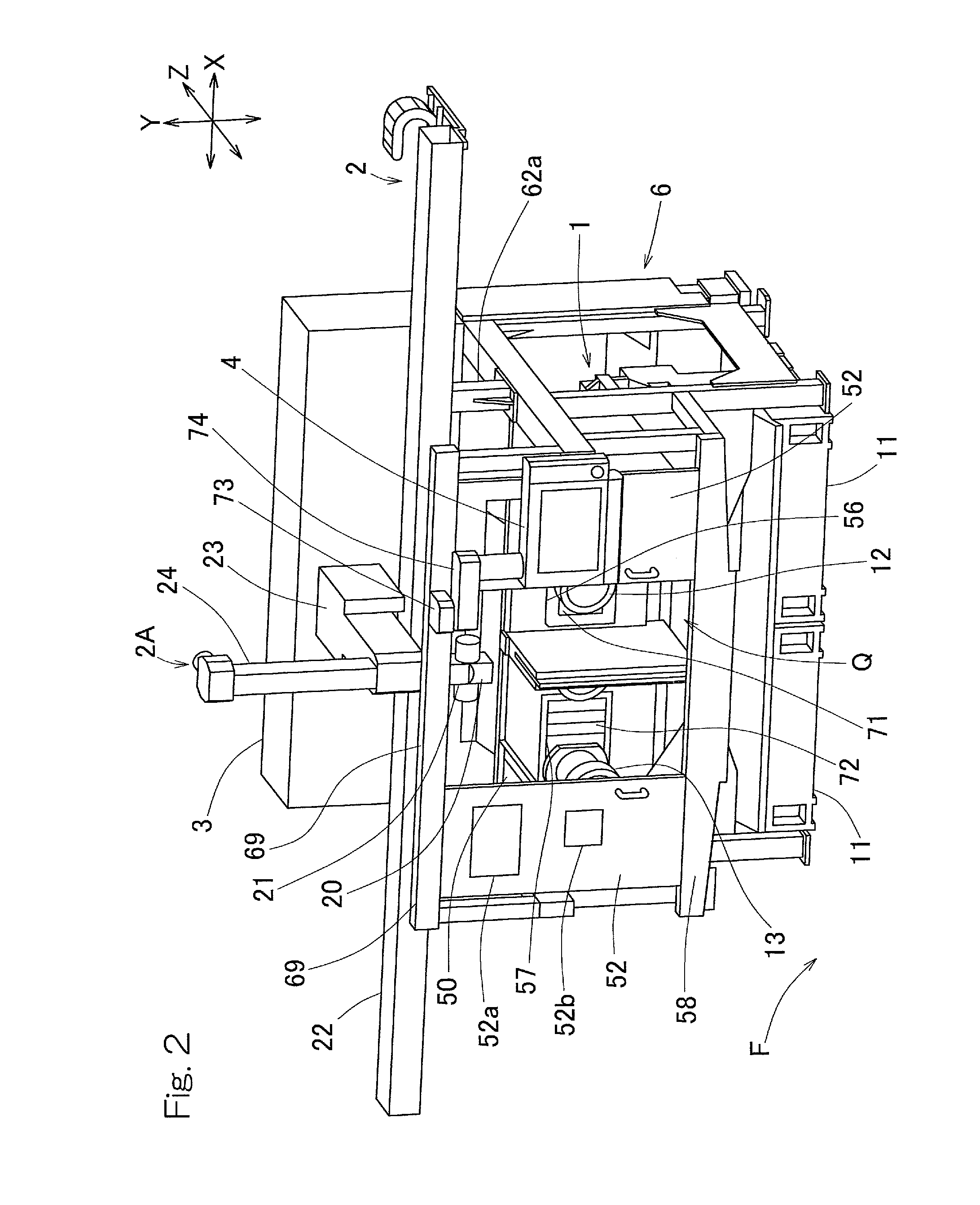
[0025]Preferred embodiments of the present invention will now be described in detail with reference to the accompanying drawings. In particular, FIG. 1 illustrates a perspective view showing the appearance of a machine tool and FIG. 2 is a view similar to FIG. 1, but with a portion of the machine tool removed. The machine tool shown in FIGS. 1 and 2 includes a machine tool main body 1, a loader apparatus 2 configured to selectively load and unload a workpiece relative to the machine tool main body 1, a control console 3 configured and programmed to control the machine tool main body 1 and the loader apparatus 2, an operating board 4 configured to operate the machine tool main body 1 and the loader apparatus 2, a shroud or covering assembly 5 configured to enclose the machine tool main body 1, and a shroud support member 6 configured to support the shroud 5. In the instance as shown in FIG. 1, the machine tool main body 1 is covered and hidden by the shroud 5 and is therefore invisib...


PUM


Abstract

A machine tool includes a machine bed, a processing machine mounted on the machine bed to perform mechanical processing on a workpiece, a covering unit configured to enclose a processing station, and a shroud support member configured to support the covering unit in a non-contact relation with the machine bed. The machine tool also includes a loader configured to travel along a rail while holding the workpiece, and configured to selectively load and unload the workpiece relative to the processing machine.

Description

[0001]This application is based on and claims Convention priority to Japanese patent application No. 2011-281062, filed Dec. 22, 2011, the entire disclosure of which is herein incorporated by reference as a part of this application.BACKGROUND OF THE INVENTION[0002]1. Field of the Invention[0003]The present invention relates to a machine tool such as, for example, a lathe and, more particularly, to a structure of a covering included in such machine tool that is configured to prevent processing from being affected by vibrations from inside and outside of a machine.[0004]2. Description of the Related Art[0005]In the conventional machine tool, a shroud or covering support member 6 is, for example, fixed to a machine bed 11 as shown in FIG. 8 and a shroud or covering (not shown) is fitted to the shroud support member 6 to enclose a processing station. The shroud support member 6 includes left and right support stands 60. In addition, in the case of the machine tool having a loader for se...

Claims


Application Information

Patent Timeline
IPC IPC(8): B23Q3/10B23Q1/03
CPCB23Q1/03B23Q3/10B23Q1/017B23Q7/04B23Q11/0891B23Q39/028B23Q41/02B23Q11/08
Inventor KOZAWA, HARUAKI
Owner MURATA MASCH LTD
Why Eureka
Try Eureka