Wireless base station and mobile station
a mobile station and base station technology, applied in the field of wireless base stations and mobile stations, can solve the problems of extreme long time needed for the transmission of ab>, and achieve the effect of reducing data portions and facilitating the maintenance of the retransmission control procedur
- Summary
- Abstract
- Description
- Claims
- Application Information
AI Technical Summary
Benefits of technology
Problems solved by technology
Method used
Image
Examples
first embodiment
(a) Description of First Embodiment
[0061] This embodiment involves devising the order in which channels are changed over upon handover.
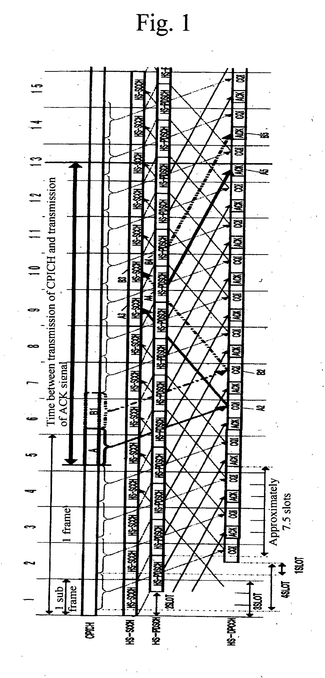
[0062] Namely, in response to the reception of a first datum (e.g. data transmitted via HS-PDSCH, which is the first channel) from a wireless base station, a mobile station transmits a second datum (e.g. a response signal (ACK signal or NACK signal) transmitted via HS-DPCCH, which is the second channel), and if the detection unit of the mobile station detects that handover is to be performed, the control unit of the mobile station provides control such that the changeover timing of the transmission destination for the second datum is made later than the changeover timing of the reception channel for the first datum.
[0063] This makes it easier for the second datum to be transmitted to the wireless base station forming the handover source wireless zone (cell).
[0064] In particular, when the response signal indicating the reception result for the firs...
second embodiment
(b) Description of Second Embodiment
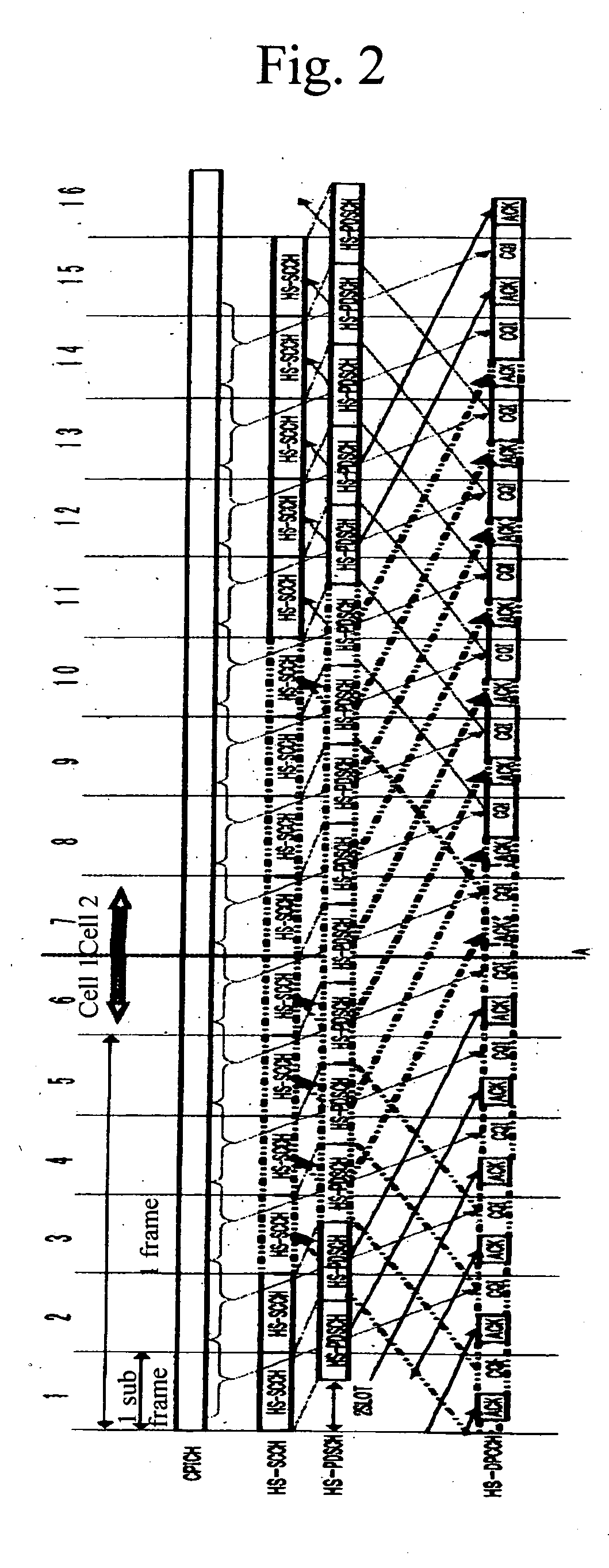
[0210] The first embodiment described the operation in a case where there is no misalignment in frame timing between the handover source and handover destination wireless zones (cells), or where it can be ignored.
[0211] The situation with a single wireless base station would likely be as in the first embodiment, since aligning the timing of frames between sectors is easy in this case.
[0212] However, the present embodiment will deal with the case where a frame timing misalignment exists between the handover source and handover destination wireless zones (cells).
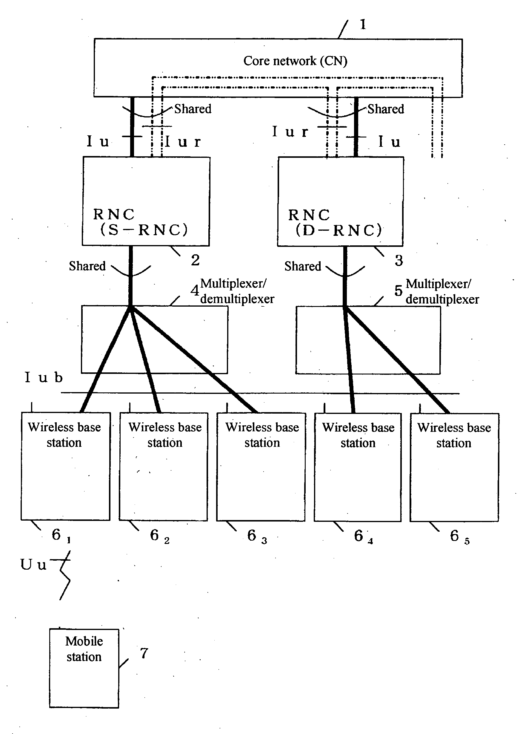
[0213] For example, handover between different wireless base stations (especially handover to a different frequency) or handover to a wireless base station subordinate to a different RNC (especially handover of a different frequency) is likely to involve a situation such as in the second embodiment.
[0214]FIG. 9 is a diagram which illustrates the frame configuration in a case where a fram...
third embodiment
(c) Description of Third Embodiment
[0223]FIG. 10 is a diagram which illustrates the frame configuration for a case where a frame timing misalignment (G in the diagram) exists between the handover source and handover destination wireless zones (cells).
[0224] In cases where there is a misalignment G in the frame timing before and after handover, processing to compensate (absorb) this misalignment is necessary.
[0225] In this embodiment, we will consider the point that transmission initiation timing C2 of HS-PDSCH which is first received from the handover destination wireless base station 6 by the mobile station 7 after changeover of the HS-PDSCH reception channel is delayed not only by two slots from the head of the sub-frame 7 but additionally by an amount G.
[0226] Here, HS-DPCCH, which is the channel on which response signals and CQI information are transmitted, is changed over in its entirety in the period between timing Dl, when transmission of response signals for HS-PDSCH tran...
PUM
 Abstract
Description
Claims
Application Information
 - R&D
- Intellectual Property
- Life Sciences
- Materials
- Tech Scout
- Unparalleled Data Quality
- Higher Quality Content
- 60% Fewer Hallucinations
Browse by: Latest US Patents, China's latest patents, Technical Efficacy Thesaurus, Application Domain, Technology Topic, Popular Technical Reports.
© 2025 PatSnap. All rights reserved.Legal|Privacy policy|Modern Slavery Act Transparency Statement|Sitemap|About US| Contact US: help@patsnap.com


