Power supply system, and power supply control method and power supply control program employed in power supply system

a power supply system and control method technology, applied in emergency power supply arrangements, secondary cells servicing/maintenance, instruments, etc., can solve the problems of attracting attention, difficult to complete all processing within a fixed amount of time, and large burden on the microcomputer, etc., to achieve the effect of shortening the monitoring period

Inactive Publication Date: 2010-07-08
PANASONIC CORP
View PDF5 Cites 19 Cited by
  • Summary
  • Abstract
  • Description
  • Claims
  • Application Information

AI Technical Summary

Benefits of technology

[0017]By means of the present invention, a power supply system, a power supply control method in a power supply system, and a power supply control program in a power supply system can be provided which, when a power supply has stopped, can continue backup functions over as long a time period as possible by reliably executing monitoring of the state of the electrical storage device.

Problems solved by technology

Further, load-leveling power supplies and plug-in hybrid vehicles which make effective use of power generated at night are attracting attention.
Further, this processing is of course executed during normal operation of the secondary battery, so that an extremely large burden is placed on the microcomputer which controls this processing.
For this reason, when the period in which the above processing is performed is shortened, it becomes difficult to complete all the processing within a fixed amount of time.
In particular, in backup applications in which the supply of energy is required up until immediately before the electrical storage device enters a dangerous state, if the state of the electrical storage device can no longer be monitored in realtime, there is the possibility that the electrical storage device may reach a dangerous state.Patent Document 1: Japanese Patent Application Laid-open No. 2006-136101

Method used


Image

  • Power supply system, and power supply control method and power supply control program employed in power supply system
  • Power supply system, and power supply control method and power supply control program employed in power supply system
  • Power supply system, and power supply control method and power supply control program employed in power supply system

Examples


embodiment 1

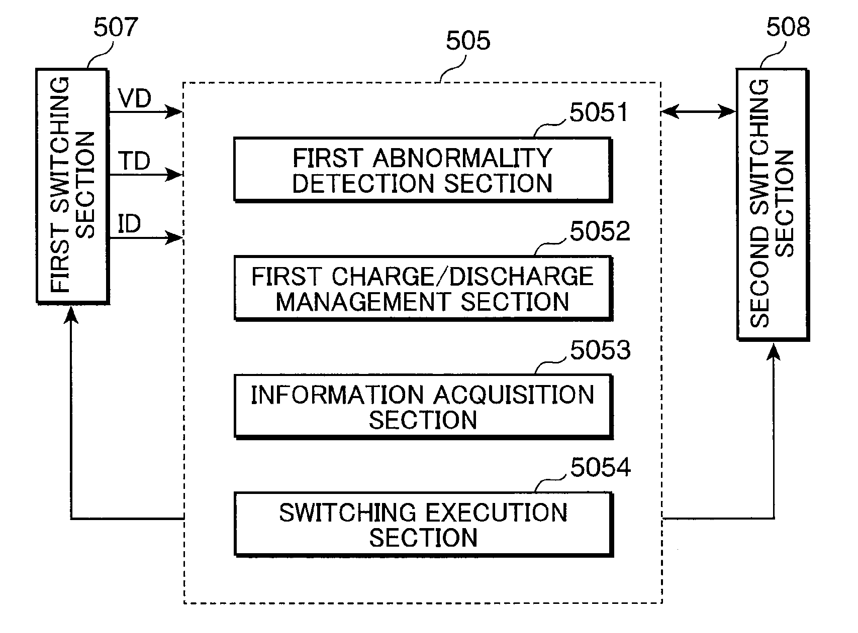
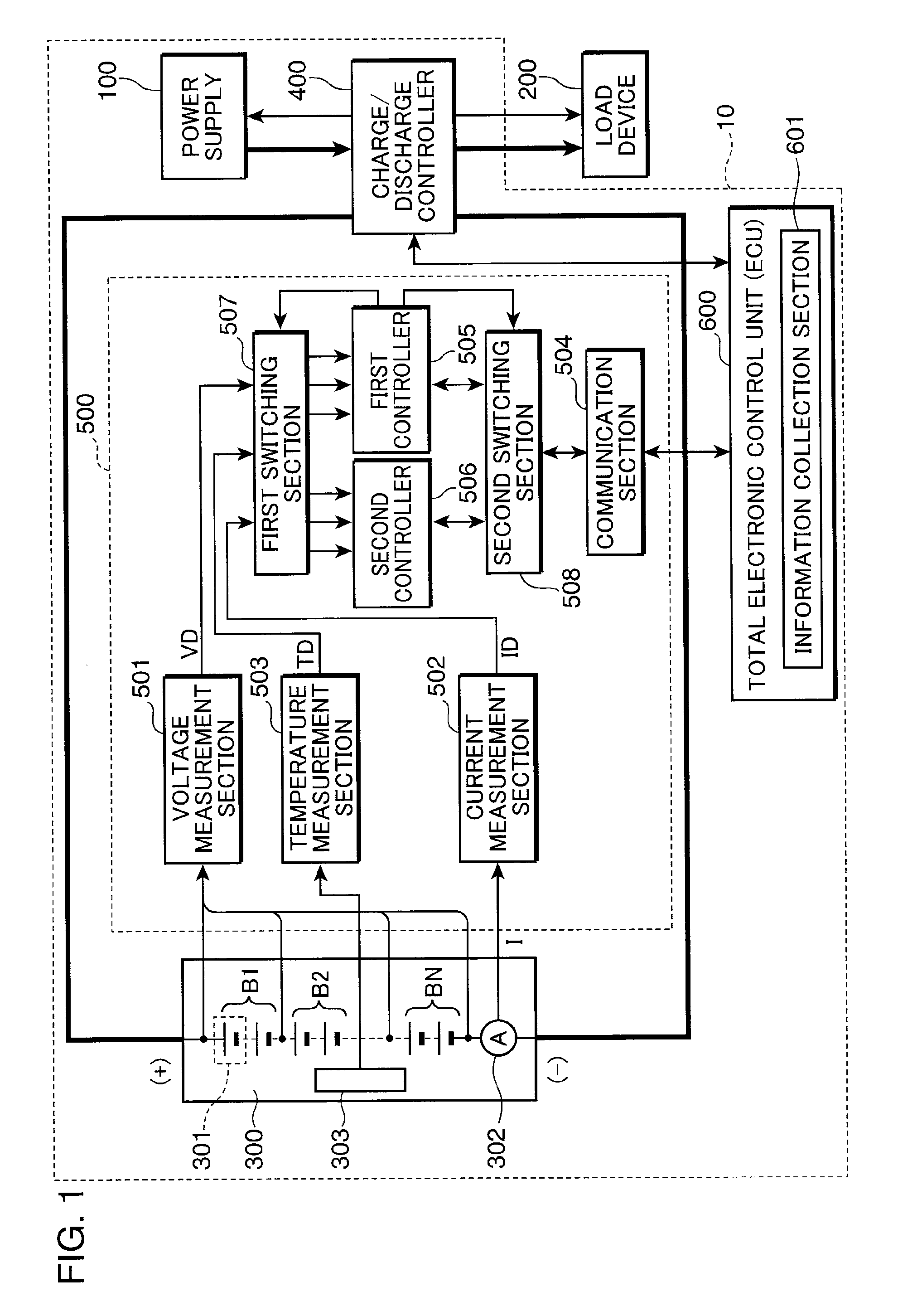
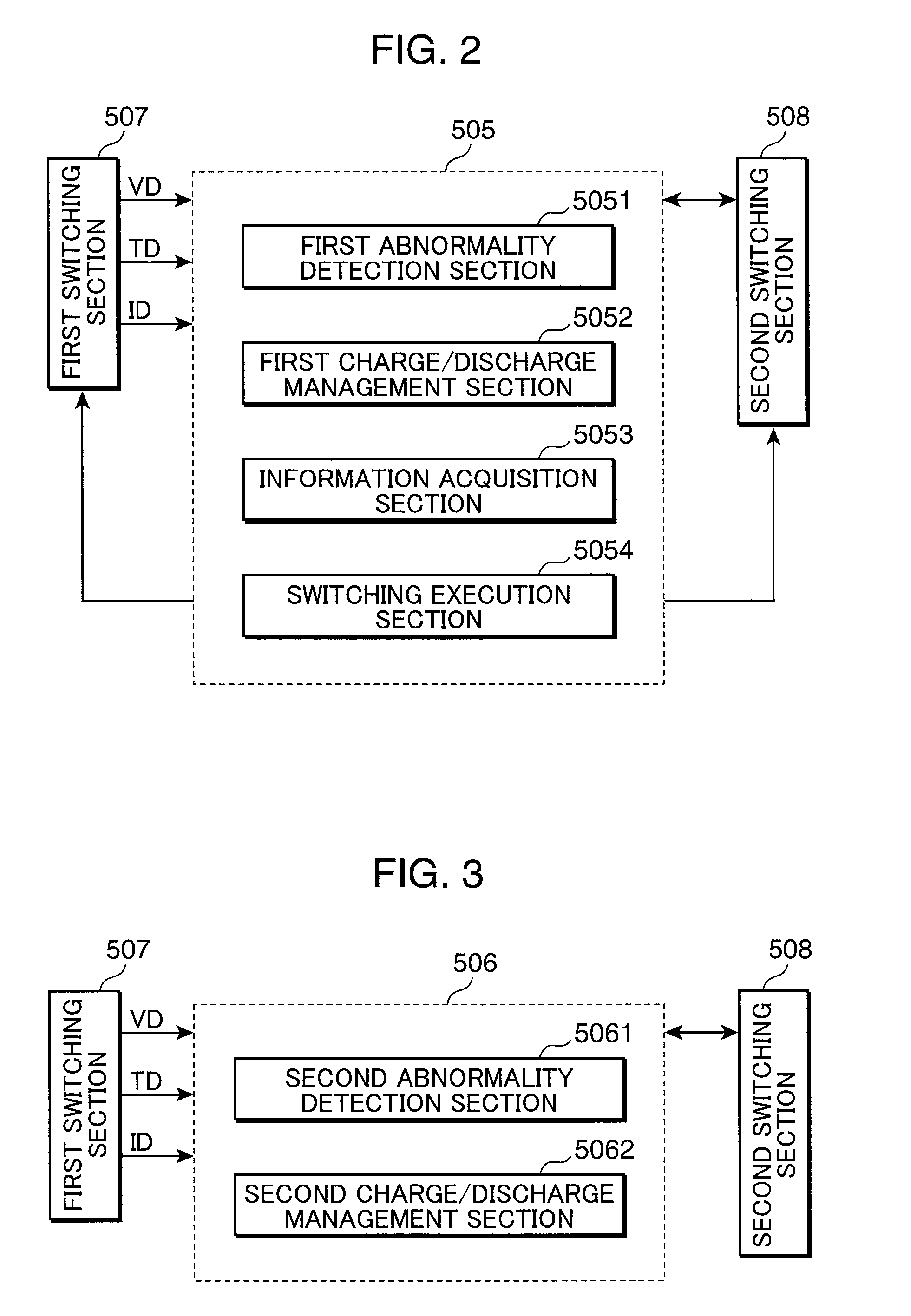
[0028]FIG. 1 is a block diagram showing the configuration of the power supply system of Embodiment 1 of the invention. As shown in FIG. 1, the power supply system 10 of the present embodiment includes a power supply 100, a storage device 300, a charge / discharge control device 400, a power supply control device 500, and a total electronic control unit (ECU) 600. The power supply system 10 may for example be a power supply system using a power generation device which generates electric power from natural energy, or a power supply system including an electrical storage device utilizing nighttime electric power such as a load leveling power supply or a plug-in hybrid vehicle, or may be a power supply system which backs up an ordinary power supply, as in a UPS or a hybrid elevator.

[0029]The power supply 100 may for example be a commercial power supply, or may be an electric generator employing an engine as the source of driving power, or similar. The load device 200 includes various load...

embodiment 2

[0073]Next, Embodiment 2 of the invention is explained. The above-described Embodiment 1 related to a power supply system in which, when stoppage information for the power supply 100 is acquired, monitoring of the state of the electrical storage device is executed reliably by shortening the period of state monitoring of the electrical storage device 300, and the backup function is continued over as long a time period as possible. On the other hand, in the present embodiment, when stoppage information for the power supply 100 has been acquired, by forcibly detaching the electrical storage device 300 from the charge / discharge control device 400 after a prescribed time has elapsed, the safety of the electrical storage device 300 and power supply system 10 is reliably secured.

[0074]FIG. 5 is a block diagram showing the configuration of the power supply system of Embodiment 2 of the invention. As shown in FIG. 5, the power supply system 10 of the present embodiment, similarly to the abov...


PUM


Abstract

A power supply system 10 comprises a power supply 100 which supplies power to a load device 200; an electrical storage device 300 which supplies power to the load device 200 in place of the power supply 100 when the power supply 100 is stopped; and a power supply control device 500 which controls the supply of power from the electrical storage device 300 to the load device 200 by monitoring a state of the electrical storage device 300 and detecting an abnormal state of the electrical storage device 300. Upon acquiring disaster information predicting stoppage of the power supply 100, the power supply control device 500 shortens a monitoring period for monitoring the state of the electrical storage device 300, so that the state of the electrical storage device 300 can be reliably monitored during stoppage of the power supply 100, and thereby backup functions can be continued over as long a time period as possible.

Description

TECHNICAL FIELD[0001]The present invention relates to a power supply system, including an electrical storage device which supplies power when a commercial power supply or other power supply has stopped, to a power supply control method of the power supply system, and to a program causing a computer to execute a power supply control method of the power supply system.BACKGROUND ART[0002]In recent years, storage devices have attracted attention and been used as backup power supplies for commercial power supplies. A backup power supply is charged when the commercial power supply is operating normally, and when an abnormality in the commercial power supply occurs, continues to supply electric power to equipment in place of the commercial power supply. A UPS (Uninterruptible Power Supply) is one such example. By instantaneously switching to the output from a backup power supply at the time of a power outage of the commercial power supply, shutdown of computers and storage devices being us...

Claims


Application Information

Patent Timeline
Patent Type & Authority Applications(United States)
IPC IPC(8): H02J9/00
CPCH01M10/425H02J9/061H01M10/44Y02E60/10
Inventor IIDA, TAKUMAKIMURA, TADAO
Owner PANASONIC CORP
Why Eureka
Try Eureka