Fast acting distributed power system for transmission and distribution system load using energy storage units

A technology of electric power and backup power, applied in the direction of control/regulation system, AC network load balance, information technology support system, etc., can solve the problem of inaccurate battery level indicator, reduce the harm of unbalanced load and reduce dependence Effect

Inactive Publication Date: 2008-06-11
OPTIMAL LICENSING CORP
View PDF0 Cites 20 Cited by
  • Summary
  • Abstract
  • Description
  • Claims
  • Application Information

AI Technical Summary

Problems solved by technology

We know that the battery level indicator seen on many commercial battery UPS systems is very inaccurate, for example it may indicate hours of available run time when in reality it may only be a few minutes

Method used


Image

  • Fast acting distributed power system for transmission and distribution system load using energy storage units
  • Fast acting distributed power system for transmission and distribution system load using energy storage units
  • Fast acting distributed power system for transmission and distribution system load using energy storage units

Examples


Embodiment Construction

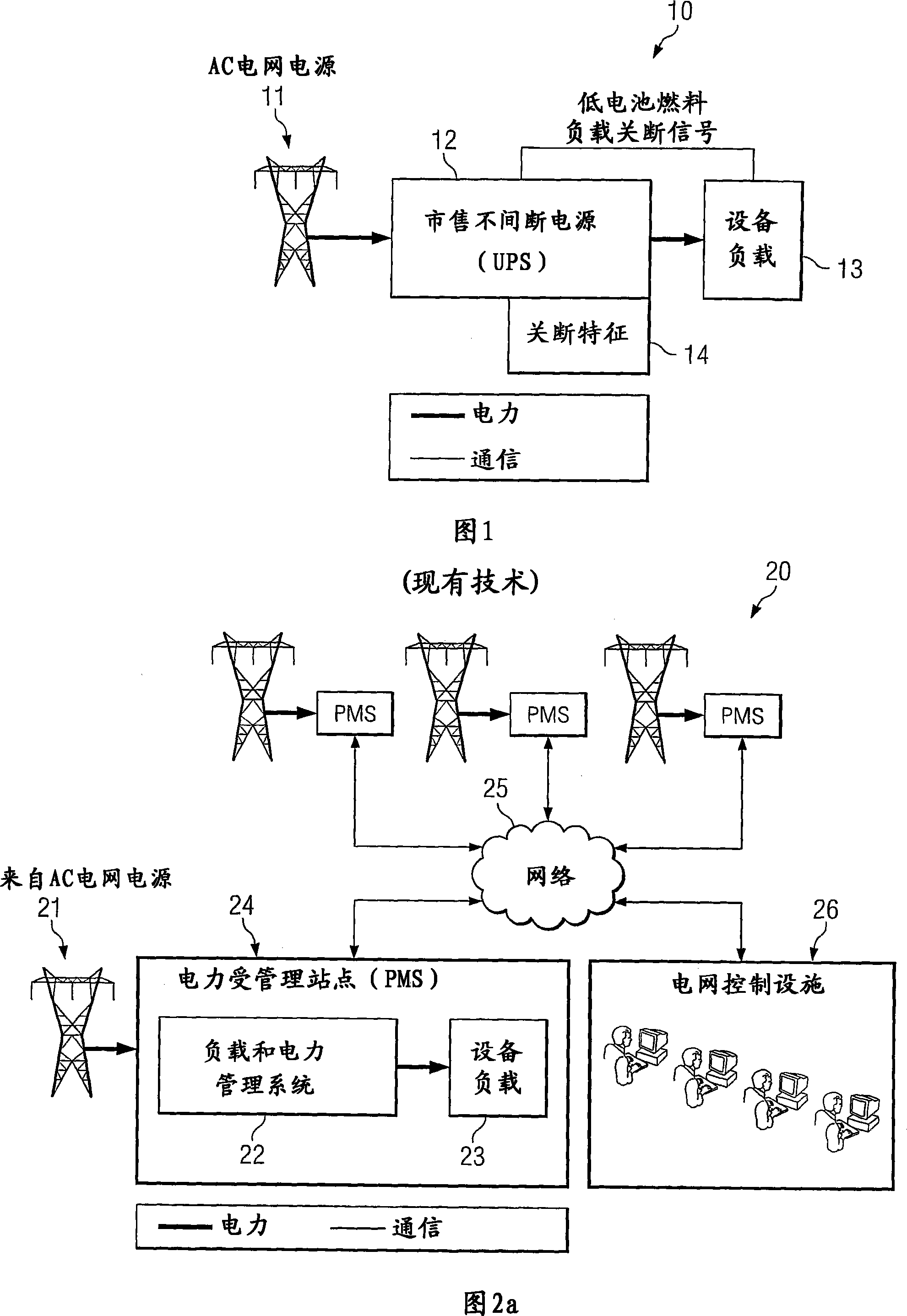
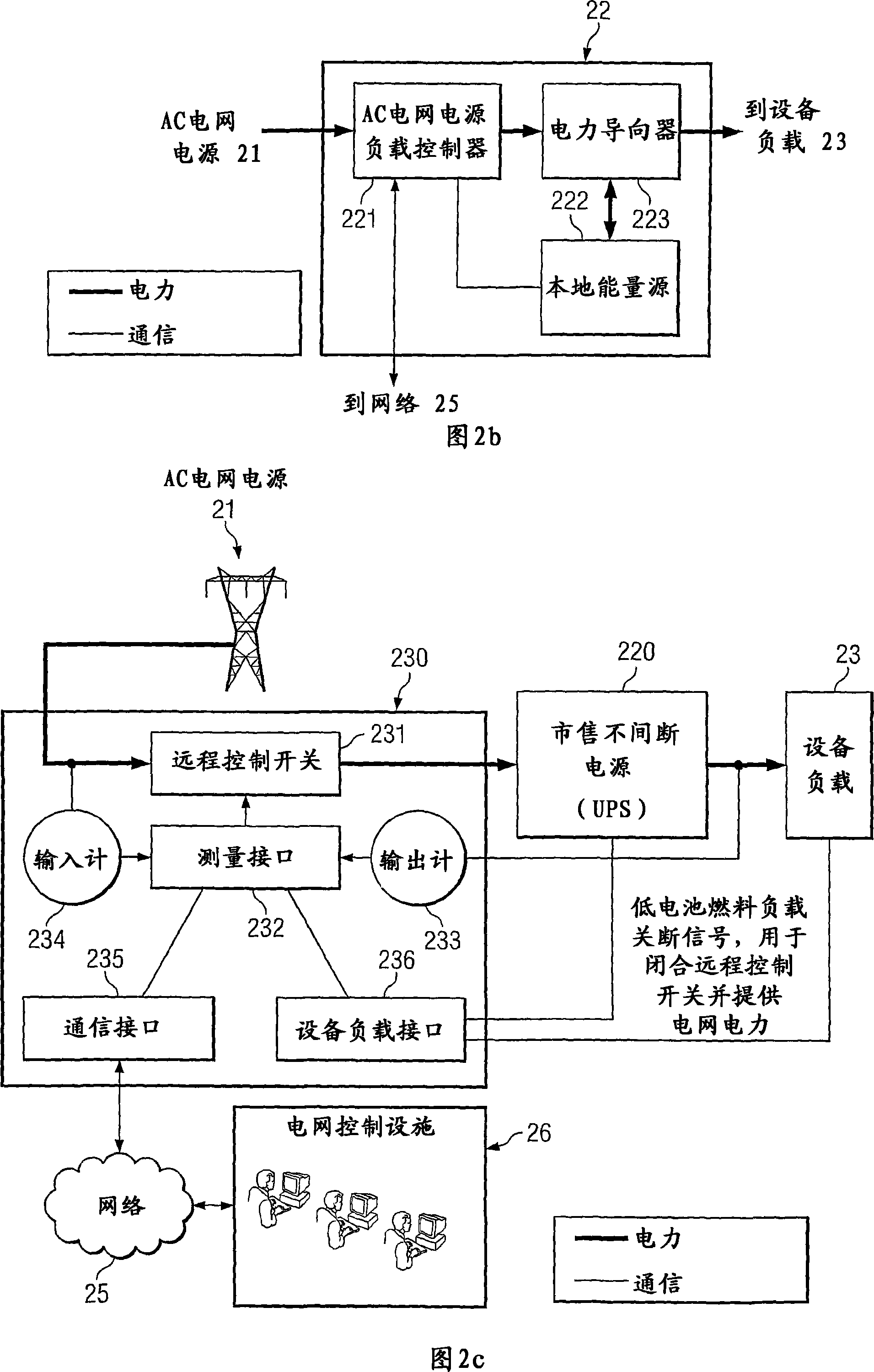
[0036] Figure 2A depicts the configuration of one embodiment of the invention. In FIG. 2A , a plurality of Power Managed Sites (PMS) are connected to an AC grid power source 21 . It should be noted that each source 21 may comprise a different grid, different parts of a grid, the same part of a grid, or a combination thereof. Each PMS 24 is also connected to a grid control facility 26 through a network 25 (which may be a wide area network). Each PMS 24 may represent a home, school, business location, other electricity consumer, or component at one of these locations. It should be noted that a site may have more than one component. Each PMS 24 includes a load management and power management system 22 and equipment loads 23 . The management system tracks the demand of the loads 23 and the amount of UPS power available at the PMS 24 and sends this information to the grid control facility 26 on a regular or continuous basis. The UPS management system 20 is used to reduce AC pow...


PUM


Abstract

An electric power load management system and method that uses a multiplicity of remote power supplies in a controlled manner such that the aggregate system has the capacity to offset critical power company peak electric demand periods thereby preventing severe and detrimental power shortages and interruptions.

Description

[0001] Cross References to Related Applications [0002] This application claims the benefit of priority to U.S. Provisional Patent Application No. 60 / 692,062, filed June 17, 2005, entitled "DISTRIBUTEDPOWER GENERATION FOR TRANSMISSION AND DISTRIBUTION SYSTEM LOAD USING UNITERRUPTIBLE POWER SOURCES," the disclosure of which is incorporated herein by reference. This application is related to co-pending and commonly assigned US Patent Application Serial No. 11 / 175,970, entitled "SYSTEM AND METHODFOR MANAGING POWER DISTRIBUTION," filed July 5, 2005, the disclosure of which is incorporated herein by reference. technical field [0003] The present invention relates to the field of utility peak demand management for reducing blackouts, brownouts, and other utility power system risks, and for providing continuous power, increased reliability, and additional Reserve capacity margins without additional transmission, distribution or generation resources that are costly and environmental...

Claims


Application Information

Patent Timeline
Patent Type & Authority Applications(China)
IPC IPC(8): H02J3/14H02J13/00
CPCH02J3/32H02J9/062Y04S20/248Y04S20/12Y02B70/30Y02B90/20H02J13/00G05D11/00
Inventor 罗兰·舍特勒詹姆士·德特默斯
Owner OPTIMAL LICENSING CORP
Why Eureka
Try Eureka