
Image coding apparatus, image coding method and image coding program

a technology of image data and coding method, applied in the field of image coding apparatus, image coding method and image coding program, can solve the problem of high calculation cos

Inactive Publication Date: 2005-09-29
KK TOSHIBA
View PDF16 Cites 23 Cited by
  • Summary
  • Abstract
  • Description
  • Claims
  • Application Information

AI Technical Summary

Problems solved by technology

However, in intra/inter mode decision utilizing the rate distortion optimization, for example, the quantity of codes generated through dynamic image coding and coding

Method used


Image

  • Image coding apparatus, image coding method and image coding program
  • Image coding apparatus, image coding method and image coding program
  • Image coding apparatus, image coding method and image coding program

Examples


Embodiment Construction

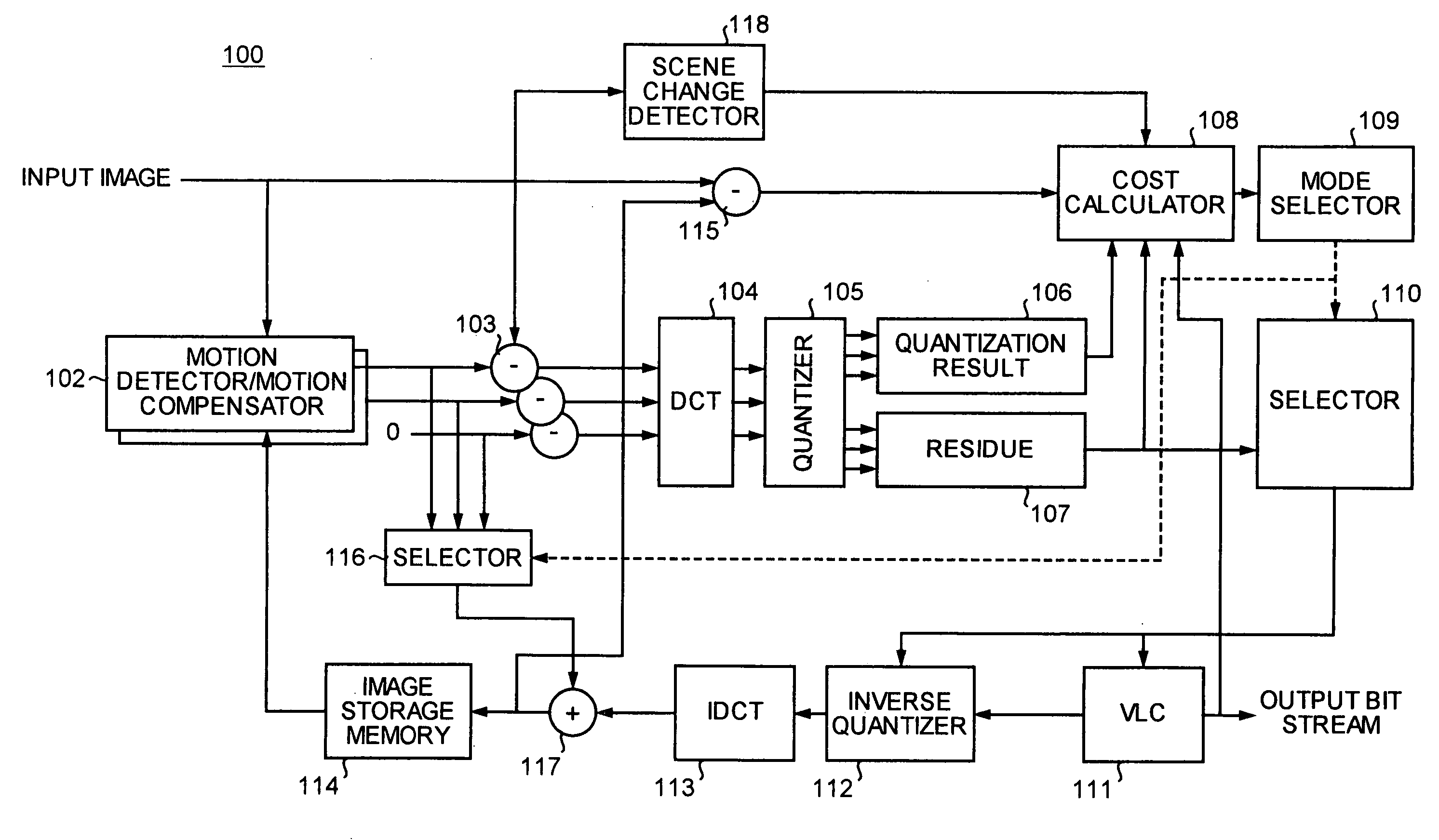
[0024] Exemplary embodiments relating to the present invention will be explained in detail below with reference to the accompanying drawings.

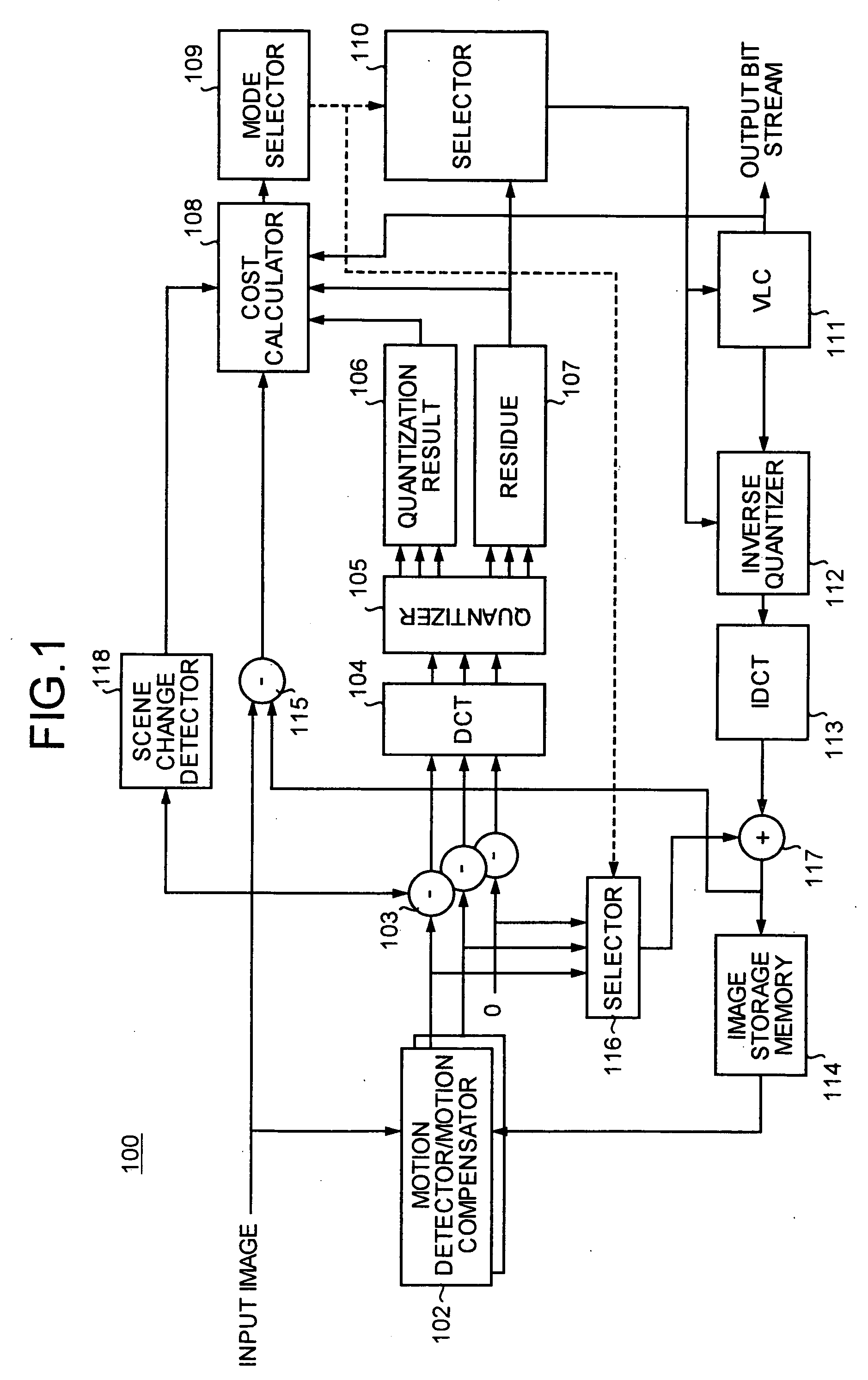
[0025]FIG. 1 is a block diagram that depicts a general configuration of an MPEG coding apparatus 100 according to an embodiment. The coding apparatus 100 according to the embodiment conducts coding process based on the ISO / IEC13818-2 (MPEG-2 Video).

[0026] The coding processing is not restricted to the ISO / IEC13818-2 (MPEG-2 Video). Other coding process, such as one based on the ISO / IEC14496-2 (MPEG-4 Video) or ISO / IEC14496-10 (MPEG-4 AVC) may be applicable.

[0027] The coding apparatus 100 includes a motion detector and motion compensator 102, a subtracter 103, a discrete cosine transformer (DCT) 104, a quantizer 105, a quantization result memory 106, a residue memory 107, a cost calculator 108, a mode selector 109, a selector 110, a variable length coder (VLC) 111, an inverse quantizer 112, an inverse discrete cosine transformer (IDCT) 113, a...


PUM


Abstract

The image coding apparatus is provided to realize image coding with little calculation quantity and through rate distortion optimization thereby maintaining a favorable image quality. The image coding apparatus includes a processing unit that conducts frequency transform and quantization on a block in a predetermined manner for a plurality of coding modes, each mode having a different coding process, a cost calculating unit that calculates a predictive coded quantity and coding distortion in a coding mode using a result of the quantization conducted by the processing unit and a residue to obtain a cost regarding the coding mode, a minimum coding cost selecting unit that selects a minimum coding cost among the coding costs calculated for respective coding modes, and a coding unit that conducts coding on the blocks in a coding mode associated with the minimum coding cost selected by the minimum coding cost selecting unit.

Description

CROSS-REFERENCE TO RELATED APPLICATIONS [0001] This application is based upon and claims the benefit of priority from the prior Japanese Patent Application No. 2004-96763; filed Mar. 29, 2004, the entire contents of which are incorporated herein by reference. BACKGROUND OF THE INVENTION [0002] 1) Field of the Invention [0003] The present invention relates to a technology for performing coding on image data. [0004] 2) Description of the Related Art [0005] With the advancement of the Large Scale Integration (LSI) technique and the computer technique, dynamic image coding typified by the Moving Picture Experts Group (MPEG)-2 and MPEG-4 has become increasingly common. With the MPEG-2 being applied to such fields as broadcasting and DVDs (Digital Versatile Discs), while the MPEG-4 being applied to portable telephones, portable video viewers, and the like, the digitization of dynamic images has become an indispensable technique today. [0006] Image coding, such as motion compensation, moti...

Claims


Application Information

Patent Timeline
IPC IPC(8): H04N7/12H04N19/50H04N19/102H04N19/12H04N19/134H04N19/136H04N19/137H04N19/142H04N19/147H04N19/154H04N19/176H04N19/196H04N19/503H04N19/577H04N19/60H04N19/61H04N19/625H04N19/91
CPCH04N19/176H04N19/147H04N19/142H04N19/103H04N19/61
Inventor KODAMA, TOMOYAMATSUMURA, ATSUSHIYAMAGUCHI, NOBORUIWATA, TATSUAKI
Owner KK TOSHIBA
Learn More