Cluster system, load distribution method, optimization client program, and arbitration server program

a load distribution and client program technology, applied in the field of cluster system, load distribution method, optimization client program, arbitration server program, can solve the problems of i/o device configuration becoming very redundant and costly, unable to process load by other nodes, and unable to solve load distribution properly, so as to prevent the effect of lowering system performan

Inactive Publication Date: 2009-11-24
NEC CORP
View PDF8 Cites 245 Cited by
  • Summary
  • Abstract
  • Description
  • Claims
  • Application Information

AI Technical Summary

Benefits of technology

[0011]Under such circumstances, it is an exemplary object of the present invention to provide a cluster system that prevents lowering of system performance to be caused by load distribution. Particularly, it is an exemplary object of the present invention to provide a cluster system capable of changing a data transfer path from a node to an I / O device dynamically.

Problems solved by technology

Thus other nodes cannot process the load.
As a result, the I / O device configuration has become very redundant and costly.
Consequently, if a problem arises in a transfer path of input / output data from an IO device to a processor, the load is not always distributed properly.
For example, even if a load is inputted to a processor that is not used efficiently and the data transfer path leading to the IO slot of the node is in congestion, the processor might not process the load.
This is why the system performance is not improved even if load distribution is made according to processor resources.
Furthermore, if an adapter card is prepared so as to enable every node to access every IO device to realize the flexible load distribution as described above, the card use efficiency falls and the cost rises.
And if only the necessary number of adapters is prepared to lower the cost, it is difficult to appropriately process the load that changes from time to time.

Method used


Image

  • Cluster system, load distribution method, optimization client program, and arbitration server program
  • Cluster system, load distribution method, optimization client program, and arbitration server program
  • Cluster system, load distribution method, optimization client program, and arbitration server program

Examples


Embodiment Construction

[0022]Hereunder, an exemplary embodiment of a cluster system of the present invention will be described with reference to the accompanying drawings. In those drawings, the same reference numerals will represent the same components, avoiding redundant description.

(Configuration)

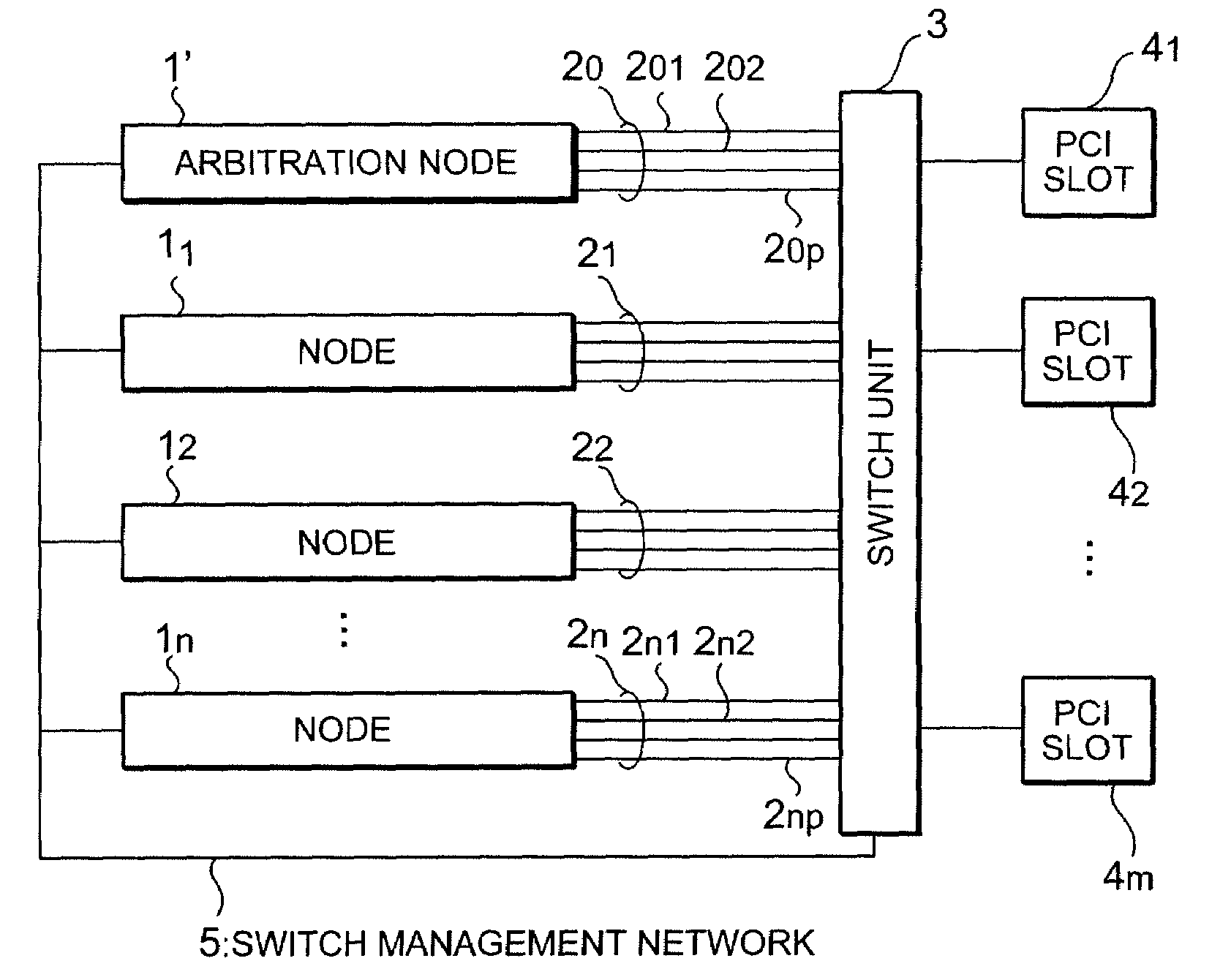
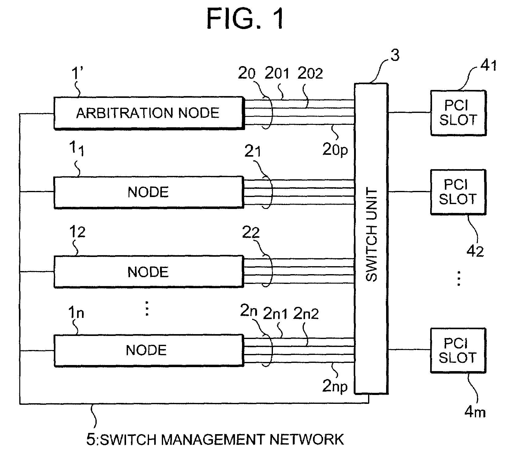
[0023]In this exemplary embodiment, a mount rack type blade server will be described as an example. FIG. 1 shows a configuration of the blade server in this exemplary embodiment of the present invention. The blade server shown in FIG. 1 includes an arbitration node 1′, plural nodes 11 to 1n, plural PCI (Peripheral Components Interconnect) buses 20 to 2n, and a switch unit 3, plural PCI slots 41 to 4m. Each PCI bus is composed of plural bus lines. For example, the PCI bus 2n has bus lines 2n1 to 2np. The arbitration node 1′ and the node 1 are computers (server blades) having a processor and a memory respectively. The arbitration node 1′ and each node 1 can be connected to each other through a PCI bus 2 and a PC...


PUM


Abstract

An exemplary cluster system according to the present invention includes a first node including a plurality of paths respectively connected to I / O slots via a switch and a second node including a plurality of paths connected to the switch, wherein the first node includes a first load measuring part which measures a first load for each path thereof, and the switch makes switching to disconnect an I / O slot from the first node and connect the I / O slot to the second node when the first load of the path connected to the I / O slot is higher than a first threshold.

Description

[0001]This application is based upon and claims the benefit of priority from Japanese patent application No. 2006-140202, filed on May 19, 2006, the disclosure of which is incorporated herein in its entirety by referenceBACKGROUND OF THE INVENTION[0002]1. Field of the Invention[0003]The present invention relates to a cluster system including plural information processing units (nodes) and a load distribution method, more particularly to a cluster system having a switch for changing the connection between each of the plurality of nodes and an I / O slot, as well as a load distribution method employed for the cluster system.[0004]2. Description of the Related Art[0005]In recent years, there has been increasing a demand of a cluster system including many information processing units (nodes) that enables processing to be continued without stopping even at the time of error occurrence, thereby improving the processing performance. In such a cluster system, the load distribution method, tha...

Claims


Application Information

Patent Timeline
Patent Type & Authority Patents(United States)
IPC IPC(8): H04L12/26
CPCH04L47/10H04L47/125H04L47/11
Inventor MIYAZAKI, MANABU
Owner NEC CORP
Why Eureka
Try Eureka