Image recognition device and method, and robot device

a robot device and image recognition technology, applied in the field of image recognition apparatus, can solve the problems of difficult to provide high-quality representation of object shapes in input images, ineffective environment recognition of objects from ordinary images, and difficult recognition, etc., to achieve the effect of stably detecting objects

Inactive Publication Date: 2005-09-29
SONY CORP
View PDF4 Cites 89 Cited by
  • Summary
  • Abstract
  • Description
  • Claims
  • Application Information

AI Technical Summary

Benefits of technology

[0025] Other and further objects, features and advantages of the present invention will appear more fully from the following description of a preferred embodiment.

Problems solved by technology

However, the technique is ineffective for an environment to recognize objects from an ordinary image subject to inconsistent viewpoints or illumination states.
Under the above-mentioned environment to recognize ordinary objects, the region division yields inconsistent results, making it difficult to provide high-quality representation of object shapes in the input image.
The recognition becomes especially difficult when the detection object is partially hidden by another object.
However, a deformed image may prevent stable extraction of the structure between feature points.
This makes it especially difficult to recognize an object partially hidden by another object as mentioned above.
However, the feature quantity used in document 1 has no constancy for enlarging or reducing images.
It is difficult to recognize images if enlarged or reduced.
However, there are several problems in the D. Lowe's technique described in document 2.
Firstly, there is a problem about the extraction of the canonical orientation at feature points.
Extracting an improper canonical orientation seriously affects a result of feature quantity matching.
Generally, however, the gradient strength is not a consistent feature quantity against brightness changes.
Fourthly, a problem may occur when the model attitude estimation section 406 estimates affine transformation parameters.

Method used


Image

  • Image recognition device and method, and robot device
  • Image recognition device and method, and robot device
  • Image recognition device and method, and robot device

Examples


Embodiment Construction

[0041] An embodiment of the present invention will be described in further detail with reference to the accompanying drawings. The embodiment is an application of the present invention to an image recognition apparatus that compares an object image as an input image containing a plurality of objects with a model image containing a model to be detected and extracts the model from the object image.

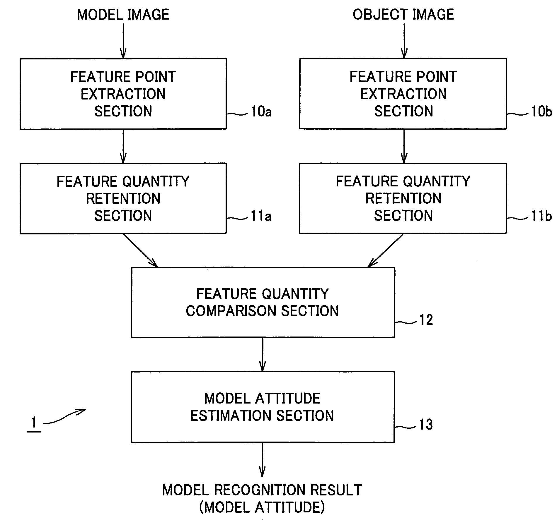
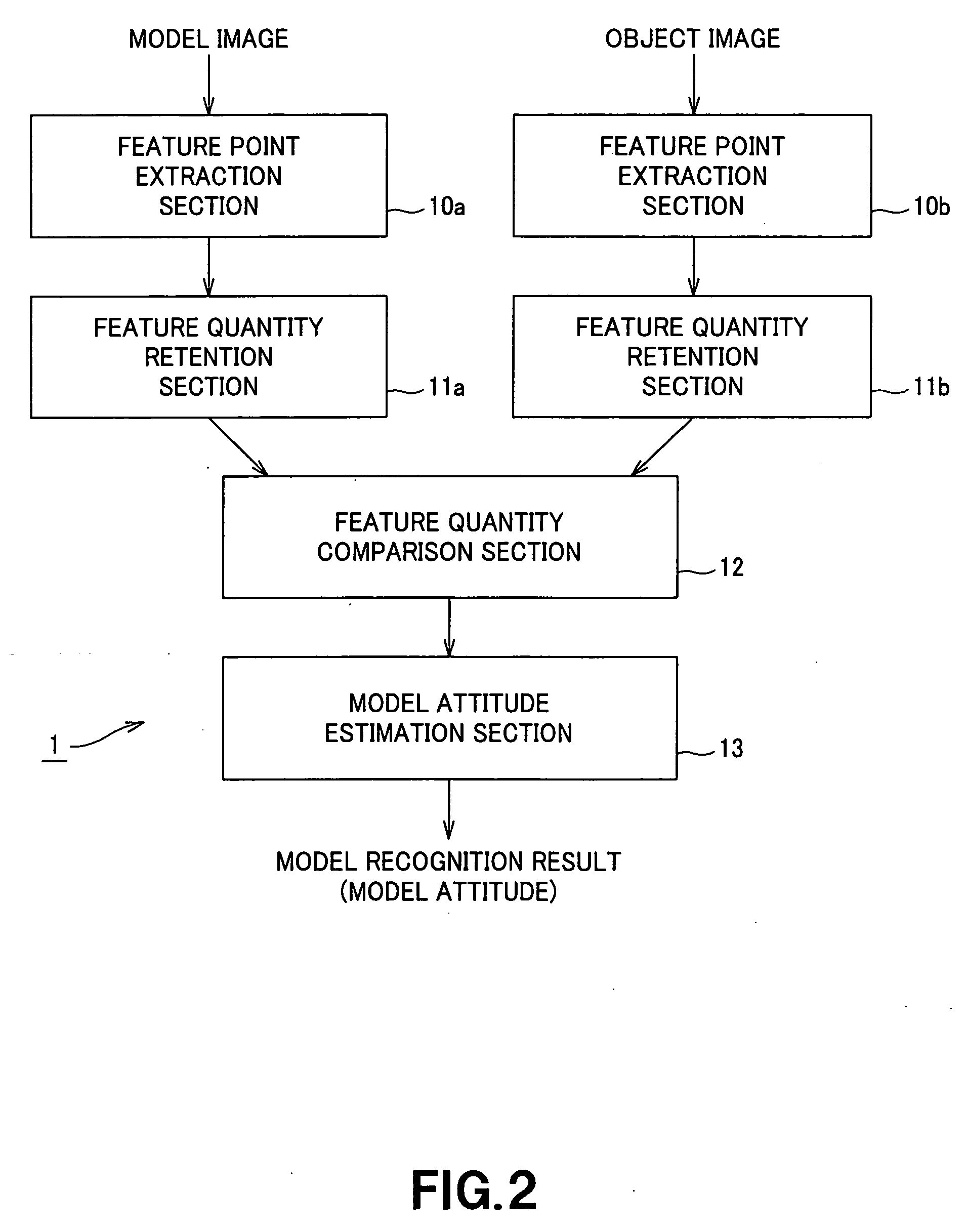
[0042]FIG. 2 shows the schematic configuration of an image recognition apparatus according to an embodiment. In an image recognition apparatus 1 of FIG. 2, feature point extraction sections 10a and 10b extract model feature points and object feature points from a model image and an object image. Feature quantity retention sections 11a and 11b extract a feature quantity for each of the extracted feature points and retain them along with positional information of the feature points. A feature quantity comparison section 12 compares the feature quantity of each model feature point with that of...


PUM


Abstract

In an image recognition apparatus (1), feature point extraction sections (10a) and (10b) extract feature points from a model image and an object image. Feature quantity retention sections (11a) and (11b) extract a feature quantity for each of the feature points and retain them along with positional information of the feature points. A feature quantity comparison section (12) compares the feature quantities with each other to calculate the similarity or the dissimilarity and generates a candidate-associated feature point pair having a high possibility of correspondence. A model attitude estimation section (13) repeats an operation of projecting an affine transformation parameter determined by three pairs randomly selected from the candidate-associated feature point pair group onto a parameter space. The model attitude estimation section (13) assumes each member in a cluster having the largest number of members formed in the parameter space to be an inlier. The model attitude estimation section (13) finds the affine transformation parameter according to the least squares estimation using the inlier and outputs a model attitude determined by this affine transformation parameter.

Description

TECHNICAL FIELD [0001] The present invention relates to an image recognition apparatus, a method thereof, and a robot apparatus installed with such image recognition function for extracting models to be detected from an object image containing a plurality of objects. [0002] The present application claims the right of priority based on Japanese Patent Application No. 2003-124225 which was applied on Apr. 28 in 2003 and is cited for the present application by reference. BACKGROUND ART [0003] Presently, many of practically used object recognition technologies use the template matching technique according to the sequential similarity detection algorithm and cross-correlation coefficients. The template matching technique is effective in a special case where it is possible to assume that a detection object appears in an input image. However, the technique is ineffective for an environment to recognize objects from an ordinary image subject to inconsistent viewpoints or illumination states...

Claims


Application Information

Patent Timeline
Patent Type & Authority Applications(United States)
IPC IPC(8): B25J5/00B25J13/08B25J19/04G06K9/46G06K9/64G06T7/00G06T7/60
CPCG06K9/4609G06T7/0042G06K9/6212G06K9/6211G06T7/73G06V10/443G06V10/758G06V10/757
Inventor SUZUKI, HIROTAKASABE, KOHTAROFUJITA, MASAHIRO
Owner SONY CORP
Why Eureka
Try Eureka