Motion estimation method under violent illumination variation based on corner matching and optic flow method

A corner point matching and illumination change technology, applied in the field of image processing, can solve the problems of rough model, no proposed motion vector misjudgment as a global motion vector, etc., to achieve high accuracy, overcome motion vector misjudgment, and good noise suppression. Effect

Inactive Publication Date: 2008-07-09
SHANGHAI JIAO TONG UNIV
View PDF0 Cites 42 Cited by
  • Summary
  • Abstract
  • Description
  • Claims
  • Application Information

AI Technical Summary

Problems solved by technology

However, this model is relatively rough and has the following shortcomings: 1. Since the picture is an infrared picture, it is implicitly assumed that if the intensity of the illumination gain changes, then the gain of each pixel must change in the same way, and the change is uniform. is linear
But this is obviously inconsistent with the non-uniform change of image light intensity when the video surveillance cameras we usually use scan from bri

Method used


Image

  • Motion estimation method under violent illumination variation based on corner matching and optic flow method
  • Motion estimation method under violent illumination variation based on corner matching and optic flow method
  • Motion estimation method under violent illumination variation based on corner matching and optic flow method

Examples


Embodiment Construction

[0023] The embodiments of the present invention are described in detail below in conjunction with the accompanying drawings: this embodiment is implemented on the premise of the technical solution of the present invention, and detailed implementation methods and specific operating procedures are provided, but the protection scope of the present invention is not limited to the following the described embodiment.

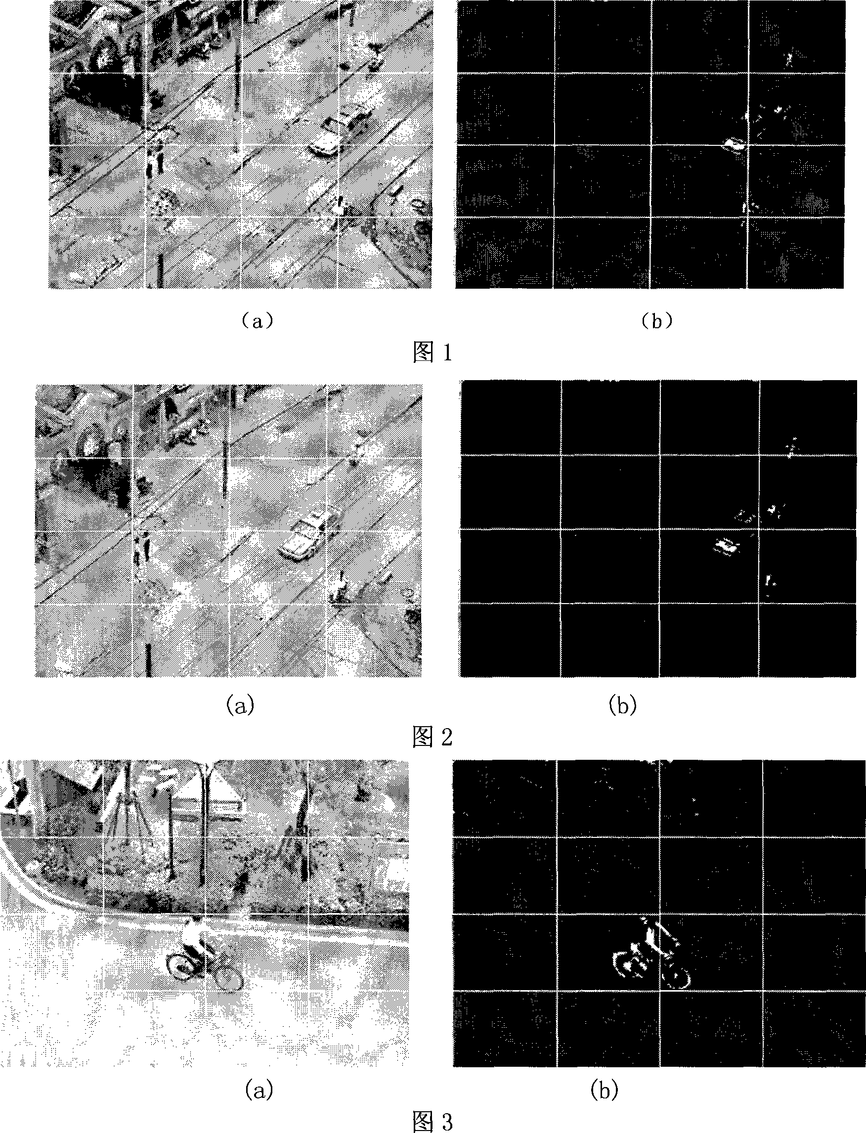
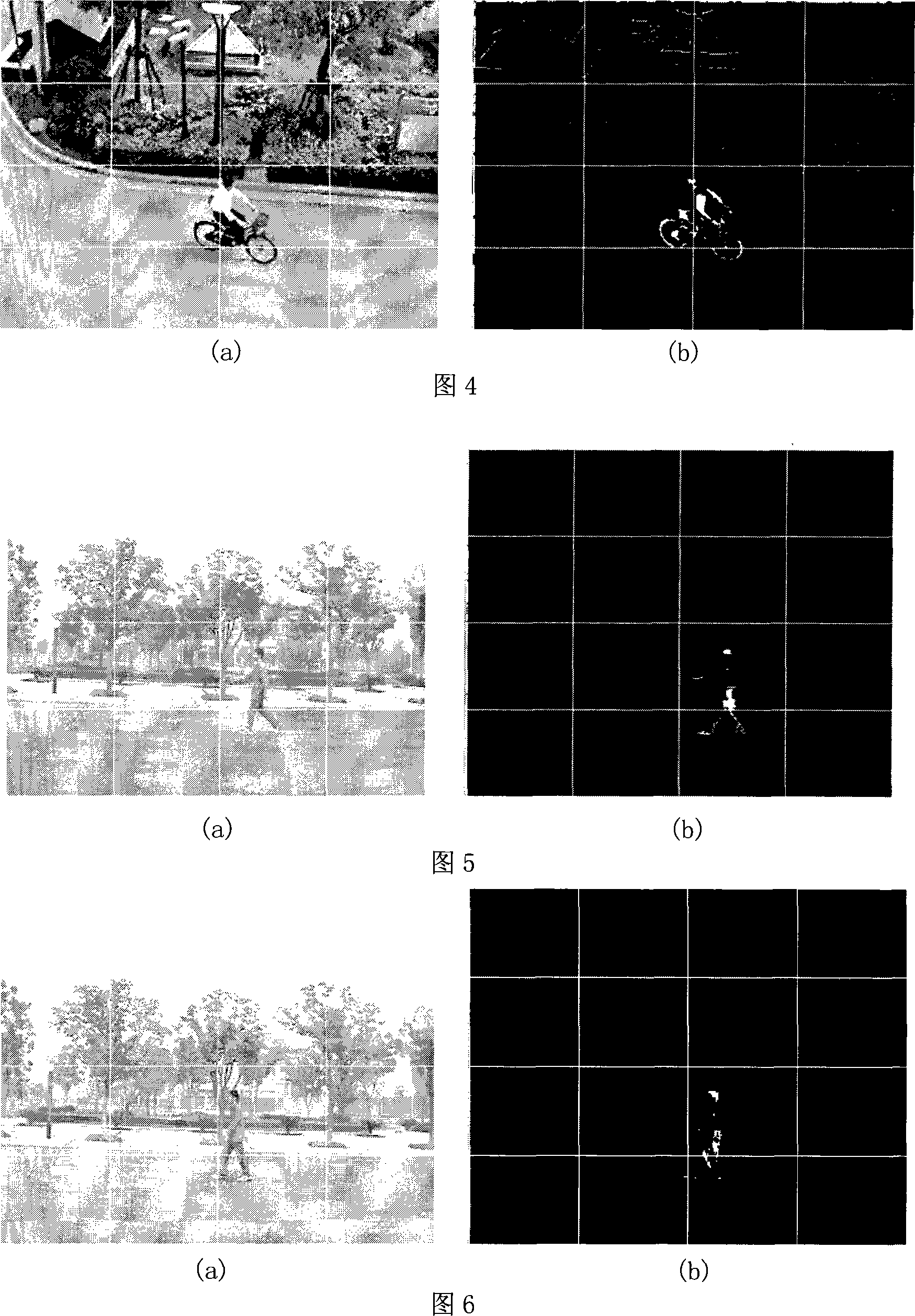
[0024] The video used in this embodiment comes from a multi-object video library with sudden changes in illumination.

[0025] This embodiment includes the following specific steps:

[0026] Step 1, using the Harris (Harris) corner detection method, the first-order or second-order difference is performed on the image, and the average square gradient matrix of each pixel is calculated: C ( x → ) = I ...


PUM


Abstract

A motion estimation method based on the angle-point matching and the optical flow method under violent light change, relating to the computer vision technology field, comprises the following steps of: first, carrying out angle-point detection to a present frame; next, carrying out normalized angle-point matching of the present frame and a last frame rotation-invariantly; then, dividing the matched frame into blocks and calculating the affine transformation parameter in each block, carrying out block global motion vector estimating of the present frame according to the affine transformation parameter and performing motion compensation of the last frame using the vector estimation; again, carrying out block linear illumination compensation of the last frame after the motion compensation; finally, estimating the global motion vector of the next frame via the optical flow computation of the linear illumination compensated image and the present image frame. With overcoming the advantages of the invalidation of the optical flow method caused by bad conditions, violent light change and great rotation, etc, the invention obtains higher accuracy.

Description

technical field [0001] The invention relates to a method in the technical field of image processing, in particular to a motion estimation method based on corner point matching and optical flow method under severe illumination changes. Background technique [0002] Optical flow method is an important method to analyze the motion of objects in sequence images, and has an extremely important application in video image analysis. When the object moves in front of the camera or the camera moves in the environment, the image will be changed. The speed distribution of the image mode movement is called optical flow, and each point on the image forms an optical flow field. However, due to the assumption of constant brightness between adjacent frames, its application range is greatly reduced. The problem of calculating the optical flow field mainly lies in two aspects: 1, the motion discontinuity caused by relative motion; 2, the drastic illumination change destroys the constant equat...

Claims


Application Information

Patent Timeline
IPC IPC(8): G06T7/00G06T7/20G06K9/00
Inventor 梁博罗青山曾贵华
Owner SHANGHAI JIAO TONG UNIV
Why Eureka
Try Eureka