A visualization method and device for measuring the accuracy of microwave reflecting surfaces

A technology of microwave reflection and precision measurement, which is applied in the antenna radiation pattern and other directions, can solve the problems of small protrusions that cannot be measured in the normal direction, judgment failure, and low efficiency, and achieve the effects of reducing human subjective assumptions, improving molds, and high efficiency

Active Publication Date: 2021-06-04
TONGYU COMM INC
View PDF8 Cites 0 Cited by
  • Summary
  • Abstract
  • Description
  • Claims
  • Application Information

AI Technical Summary

Problems solved by technology

[0004] If mechanical measurement is used, only the normal gap between the curved backing plate and the reflective surface to be measured can be measured, but the tiny protrusions in the normal direction cannot be measured, and the contact between the curved backing plate and the measured reflective surface will affect the accuracy of the opposite surface due to gravity. a certain degree of influence;
[0005] The root mean square value is used to judge the accuracy of the reflective surface. This index is a macro-average value. For the judgment of the accuracy of the reflective surface with local severe deformation, judgment failure may occur;
[0006] This measurement method is inefficient, difficult to image, and intuitively reflects the accuracy of the reflective surface. During the measurement process, many subjective factors of the measurer are involved, and it is difficult to achieve the purpose of objectively evaluating the accuracy of the reflective surface.

Method used


Image

  • A visualization method and device for measuring the accuracy of microwave reflecting surfaces
  • A visualization method and device for measuring the accuracy of microwave reflecting surfaces
  • A visualization method and device for measuring the accuracy of microwave reflecting surfaces

Examples


Embodiment Construction

[0035] The preferred embodiments of the invention are given below in conjunction with the accompanying drawings to describe the technical solutions of the present invention in detail. Here, the present invention will be described in detail with reference to the accompanying drawings. It should be noted that the preferred implementation examples described here are only used to illustrate and explain the present invention, and are not used to limit or limit the present invention.

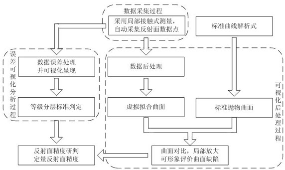
[0036] A visualization method for measuring the accuracy of microwave reflective surfaces:

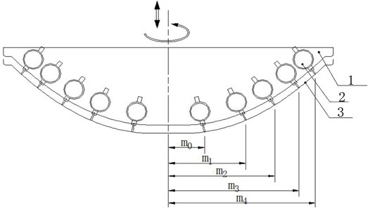
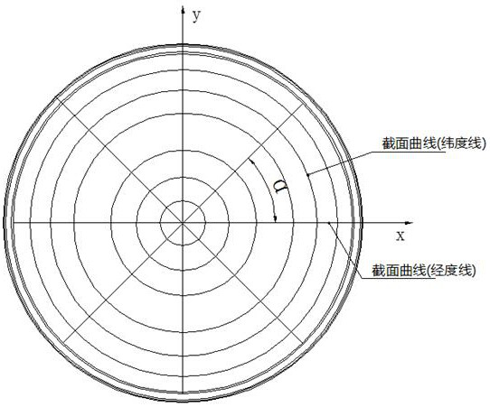
[0037] Step 1. Contact multiple measuring instruments with local points on the measured microwave reflective surface at normal angles, and calculate the actual measured normal parameters with the measured data of the measured points

[0038] In current engineering, it is usually used to measure the accuracy of the reflective surface by using the combination of the curve plate and the feeler gauge. This meas...


PUM


Abstract

A method and device for visualizing the accuracy measurement of a microwave reflecting surface, which adopts local point contact and automatic collection methods to collect data points on the reflecting surface, record the normal value points of the reflecting surface, and compare the values ​​of the actual microwave reflecting surface and the standard microwave The values ​​of the reflective surface are fitted according to the longitude and latitude directions, and the comparison and visualization results of the standard microwave reflective surface and the measured microwave reflective surface are obtained. This method is local contact, which will not affect the accuracy of the reflective surface itself, and overcomes the The mechanical measurement method cannot measure the shortcomings of the tiny protrusions in the normal direction, and through corresponding special calculations, the corresponding visualization results are obtained through software.

Description

technical field [0001] The invention relates to a microwave antenna measurement technology, in particular to a method and device for visually realizing the precision measurement of a microwave reflecting surface. Background technique [0002] As one of the important terminals of the communication system, the microwave antenna is widely used in point-to-point wireless communication. The parabolic antenna is one of the most common implementation methods in the microwave field. The reflective surface is the core component of the parabolic antenna. Performance indicators are good or bad. [0003] In current projects, mechanical measurement is usually used to measure the accuracy of the reflective surface. At present, the curve plate and feeler gauge are often used to measure the normal clearance value L of evenly distributed points. i , and calculate its root mean square However, with this method, there are the following problems: [0004] If mechanical measurement is used, ...

Claims


Application Information

Patent Timeline
Patent Type & Authority Patents(China)
IPC IPC(8): G01R29/10
CPCG01R29/10
Inventor 刘彬彬陈鹏羽熊国辉粟炳龙李骁男许超磊林泽银郭浩楠
Owner TONGYU COMM INC
Why Eureka
Try Eureka