Air compressor

Inactive Publication Date: 2005-09-29
TSAI CHUNG SHENG
View PDF5 Cites 23 Cited by
  • Summary
  • Abstract
  • Description
  • Claims
  • Application Information

AI Technical Summary

Benefits of technology

[0005] The primary purpose of the present invention is to provide an improved structural configuration of an air compressor that is portable for field op

Problems solved by technology

Though it is not very difficult to have power supply as a fixed power socket is available in the room where the work is provided in a fixed place, it usually takes a length extensi

Method used


Image

  • Air compressor
  • Air compressor
  • Air compressor

Examples


Embodiment Construction

[0013] The following descriptions are of exemplary embodiments only, and are not intended to limit the scope, applicability or configuration of the invention in any way. Rather, the following description provides a convenient illustration for implementing exemplary embodiments of the invention. Various changes to the described embodiments may be made in the function and arrangement of the elements described without departing from the scope of the invention as set forth in the appended claims.

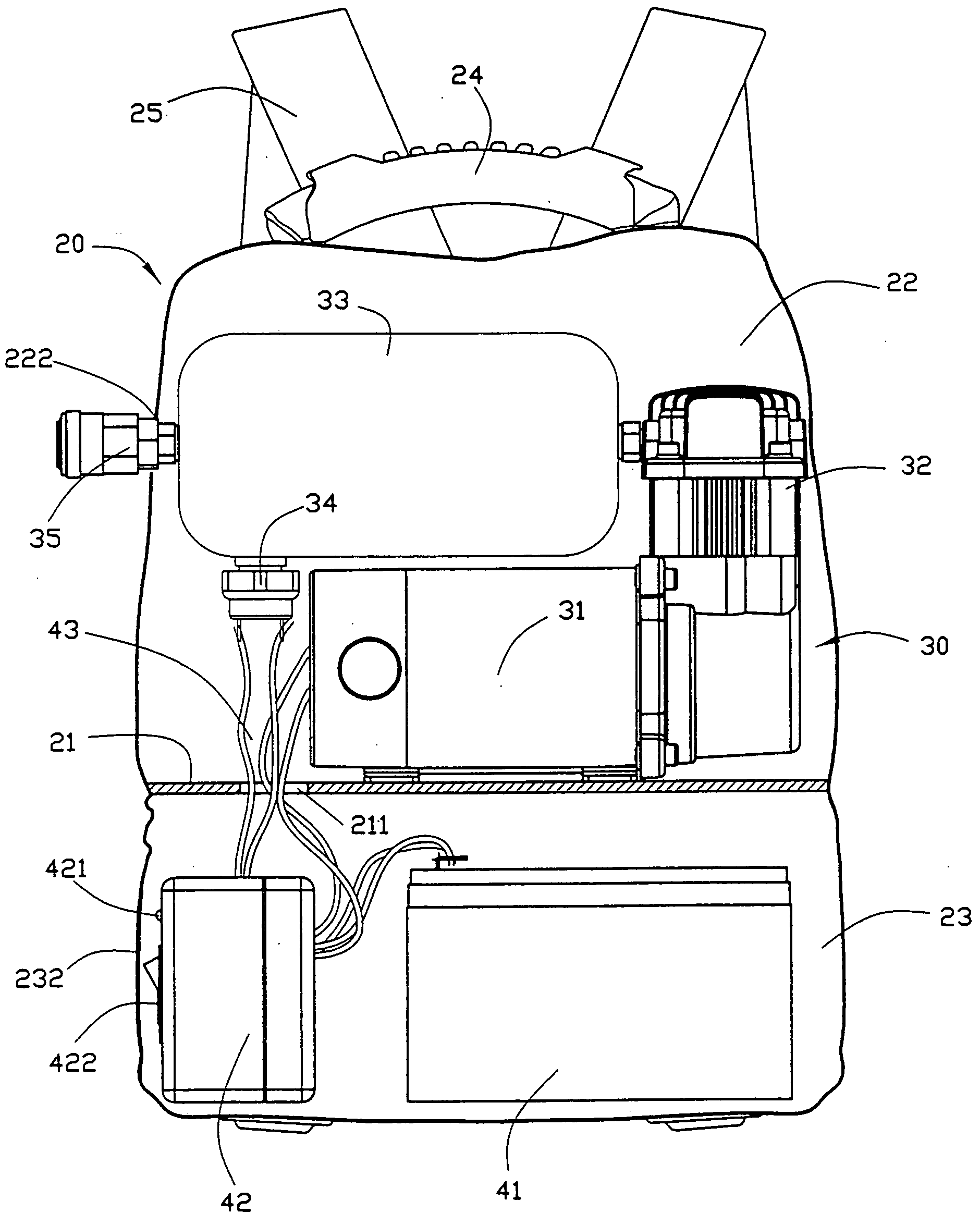
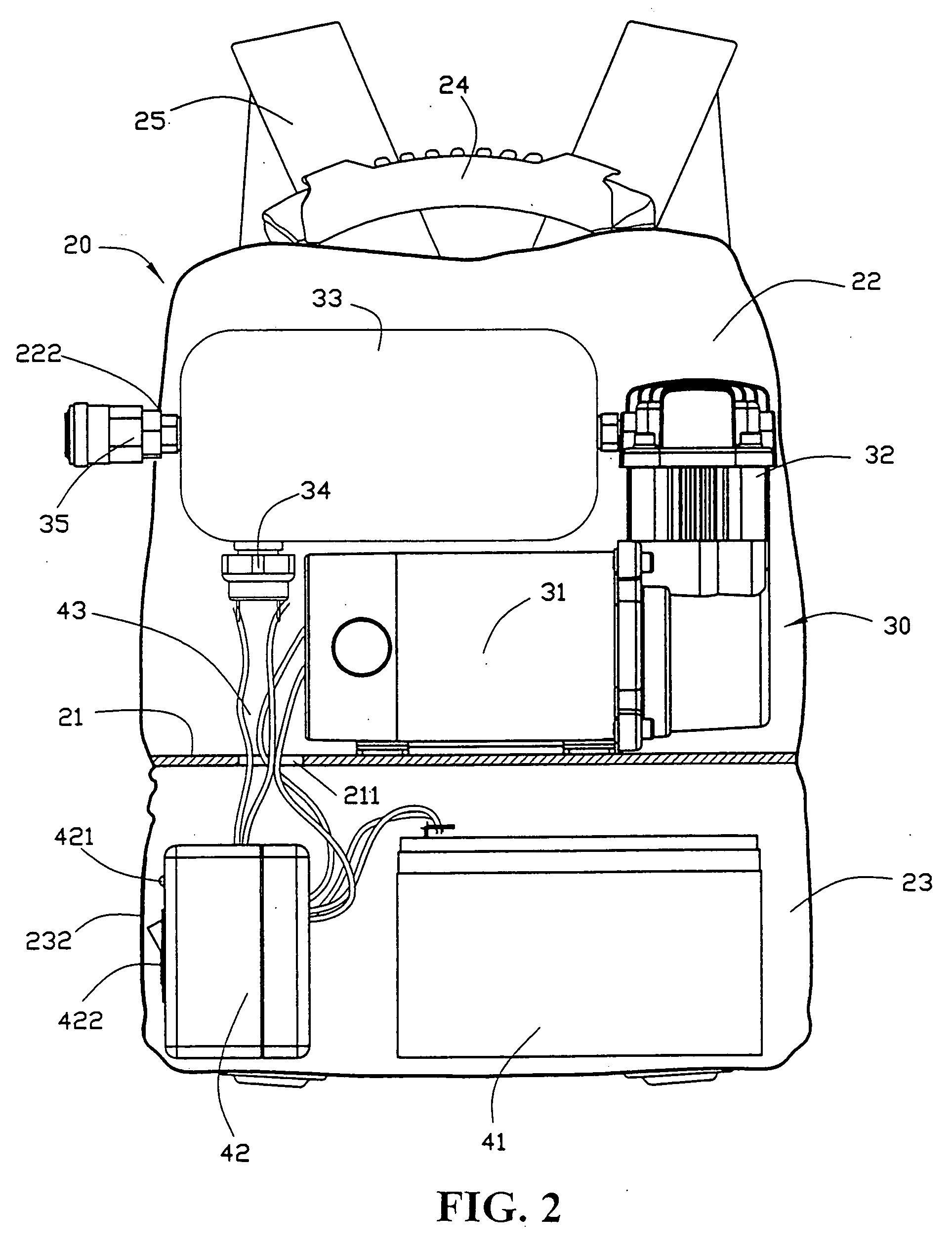
[0014] Referring to FIGS. 2 through 5, a preferred embodiment of an improved air compressor of the present invention is essentially comprised of an interlayer (21) provided with a through hole (211) inside a knapsack (20), an upper chamber (22) sewn with a longitudinal zipper (221) to its peripheral and a lower chamber (23) sewn with a lateral zipper (231) with both chambers 22, 23 segregated by the interlayer (21).

[0015] The upper chamber (22) accommodates components (30) including a DC motor...


PUM


Abstract

An air compressor for field use comprised of an interlayer in a knapsack to segregate an upper chamber and a lower chamber, both zipped, the upper chamber accommodating multiple components including DC motor, air cylinder, air storage flask, pressure switch and fast connector; a through hole being disposed on the side of the upper chamber to expose the fast connector to plug into an air delivery hose from a pneumatic tool; the lower chamber accommodating the battery and the control box; a see-through window being sewn on the side of the lower chamber; handler, carrying belt and shoulder belt being provided to the knapsack.

Description

BACKGROUND OF THE INVENTION [0001] (a) Technical Field of the Invention [0002] The present invention is related to a structural configuration of an air compressor, and more particularly, to an improved air compressor that is portable to allow filed operation. [0003] (b) Description of the Prior Art [0004] As illustrated in FIG. 1 of the accompanying drawings for the prior art, a compressor (12) operating on AC power is adapted to the top of an air storage tank, meaning an AC power source must be available in the vicinity of the work place. Though it is not very difficult to have power supply as a fixed power socket is available in the room where the work is provided in a fixed place, it usually takes a length extension wire that may make the process of work awkward. Whereas the use of high pressure air is not limited to a fixed work place, there are many occasions the work is done in a rather stranger place, namely, deflation for motor vehicles, removal of a tire using a power tool ...

Claims


Application Information

Patent Timeline
IPC IPC(8): F02G3/00F04B41/02
CPCF04B41/02
Inventor TSAI, CHUNG-SHENG
Owner TSAI CHUNG SHENG
Why Eureka
Try Eureka