Retracting needle safety device

a safety device and needle tip technology, applied in the field of needle assembly, can solve the problem of not providing effective protection at the non-patient tip of the needle within the housing

Inactive Publication Date: 2005-09-29
BECTON DICKINSON & CO
View PDF43 Cites 73 Cited by
  • Summary
  • Abstract
  • Description
  • Claims
  • Application Information

AI Technical Summary

Benefits of technology

[0016] A lock mechanism may also be provided by including at least one, and preferably two fin fingers extending from each fin, and by including at least one and preferably two corresponding notches within each guide channel. The fin fingers and the corresponding notches can be moved to a position of interference engagement when the retraction assembly is in the second position, thereby acting as a locking mechanism to prevent the retraction assembly from moving from the second position back to the first position. The guide channel may also include a stop extending from an interior surface of the wall within the guide channel, with the stop desirably including a forward ramped surface and a rearward shoulder. The forward ramped surface causes the fin to radially flex when the fin contacts the stop during movement of the retraction assembly from the first position to the second position, and the shoulder provides for interference engagement with the fin when the retraction assembly is in the second position to prevent the fin from moving within the guide channel, thereby preventing the retraction assembly from moving from the second position to the first position.
[0017] The guide channel may also include a recess extending within the wall of the outer body at a rearward portion of the guide channel, with the fin adapted for radial outward flexing for engagement with the recess when the retraction assembly is in the second position, thereby preventing the fin from moving within the guide channel and preventing the retraction assembly from moving from the second position to the first position.

Problems solved by technology

Such an assembly requires multiple movements of the needle carrier by the operator to retract and to pivot and bend the needle, and does not provide effective protection at the non-patient tip of the needle within the housing.

Method used


Image

  • Retracting needle safety device
  • Retracting needle safety device
  • Retracting needle safety device

Examples


Embodiment Construction

[0035] While the present invention is satisfied by embodiments in many different forms, there is shown in the drawings and will herein be described in detail, the preferred embodiments of the invention, with the understanding that the present disclosure is to be considered as examplary of the principles of the invention and is not intended to limit the invention to the embodiments illustrated. Various other embodiments will be apparent to and readily made by those skilled in the art without departing from the scope and spirit of the invention. The scope of the invention will be measured by the appended claims and their equivalents.

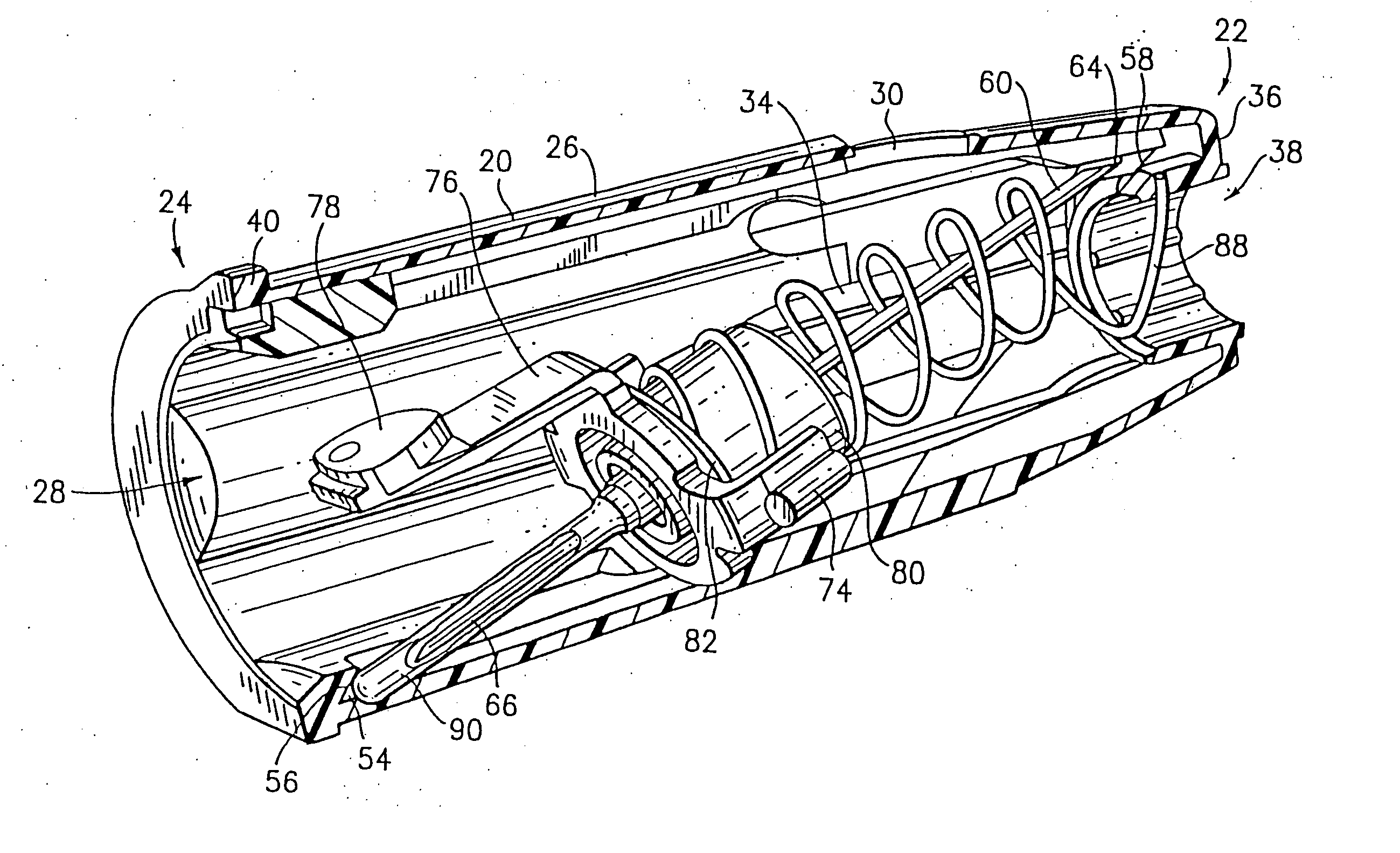
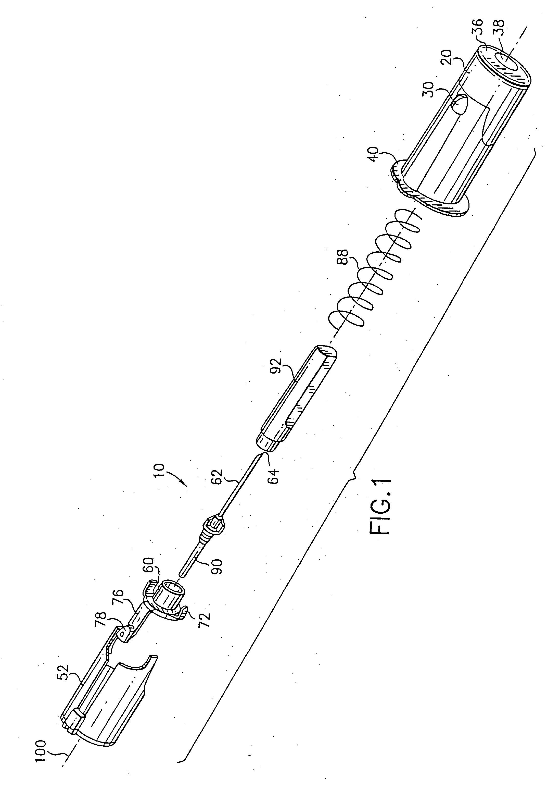
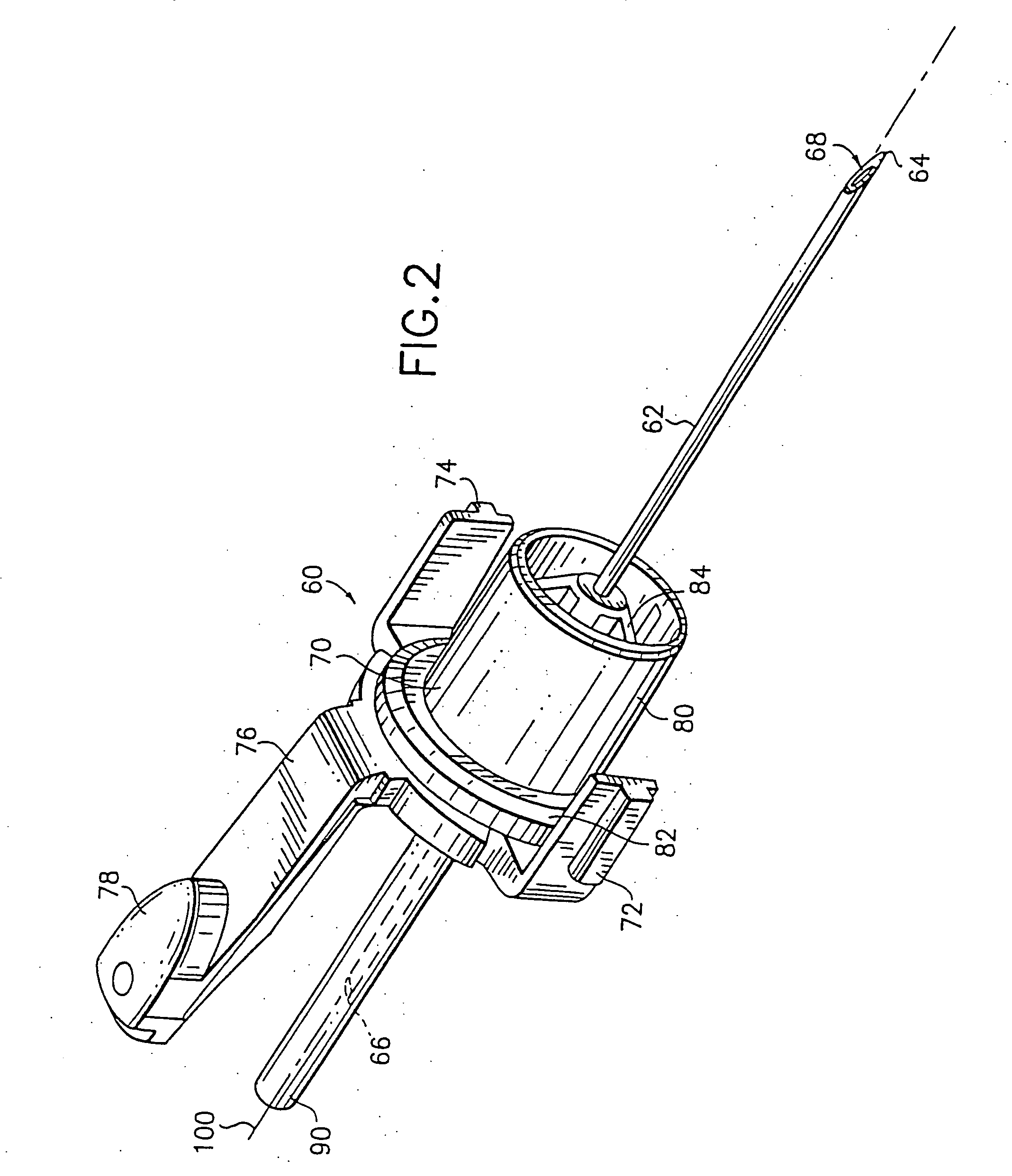
[0036] The present invention is generally directed to a retracting safety needle assembly, which allows for safe and convenient retraction of a phlebotomy needle, such as a double-ended needle, into a holder device. Generally speaking, retraction of the needle is accomplished by activating a button on the assembly, which enables a spring member to force a...


PUM


Abstract

A retractable safety needle assembly is provided. The needle assembly includes a tubular outer body, a retraction assembly contained with the outer body and a biasing element for applying a retraction force therebetween. The retraction assembly includes a cannula having an intravenous puncture tip and a non-patient puncture tip at opposing ends. In a first position, the intravenous puncture tip extends from a first end of the tubular outer body. The retraction assembly is adapted for movement within the tubular outer body from the first position to a second position in which the intravenous puncture tip and the non-patient puncture tip are contained entirely within the tubular outer body and are offset from a general axis defining the outer body.

Description

CROSS-REFERENCE TO RELATED APPLICATION [0001] This application claims the benefit of earlier filed U.S. Provisional Patent Application Ser. No. 60 / 311,006 filed Aug. 9, 2001, entitled “Retracting Needle Safety Device”.BACKGROUND OF THE INVENTION [0002] 1. Field of the Invention [0003] The present invention relates to a needle assembly having safety elements for safe and convenient handling. More particularly, the present invention relates to a needle assembly having a double-ended needle for collecting or delivering fluid samples from or into a patient and which includes a retracting assembly for retraction of the needle. [0004] 2. Description of Related Art [0005] Disposable medical devices having piercing elements are typically used for administering a medication or withdrawing a fluid, such as blood collecting needles, fluid handling needles and assemblies thereof. Current medical practice requires that the fluid containers and needle assemblies used in such systems be inexpensiv...

Claims


Application Information

Patent Timeline
Patent Type & Authority Applications(United States)
IPC IPC(8): A61B5/15A61M5/158A61M5/32
CPCA61B5/15003A61B5/150389A61B5/150496A61B5/150572A61B5/150656A61B5/150717A61B5/150732A61B5/153A61M5/3232A61M2005/3224A61M5/32
Inventor SAULENAS, WILLIAMSULLIVAN, MICHELLEWILKINSON, BRADLEYSWENSON, KIRK
Owner BECTON DICKINSON & CO
Why Eureka
Try Eureka