Infusion set and injector device for infusion set

a technology of injector device and infusion set, which is applied in the field of infusion set, can solve the problems of relatively complicated industrial manufacturing of infusion device, and achieve the effect of less discomfort for patients and convenient operation for patients

Active Publication Date: 2005-09-29
UNOMEDICAL AS
View PDF99 Cites 134 Cited by
  • Summary
  • Abstract
  • Description
  • Claims
  • Application Information

AI Technical Summary

Benefits of technology

[0013] The object of the invention is to provide an infusion set with a coupling mechanism which can be connected and separate...

Problems solved by technology

However the apparatus is relatively complicated to manufacture industrially and furt...

Method used


Image

  • Infusion set and injector device for infusion set
  • Infusion set and injector device for infusion set
  • Infusion set and injector device for infusion set

Examples


first embodiment

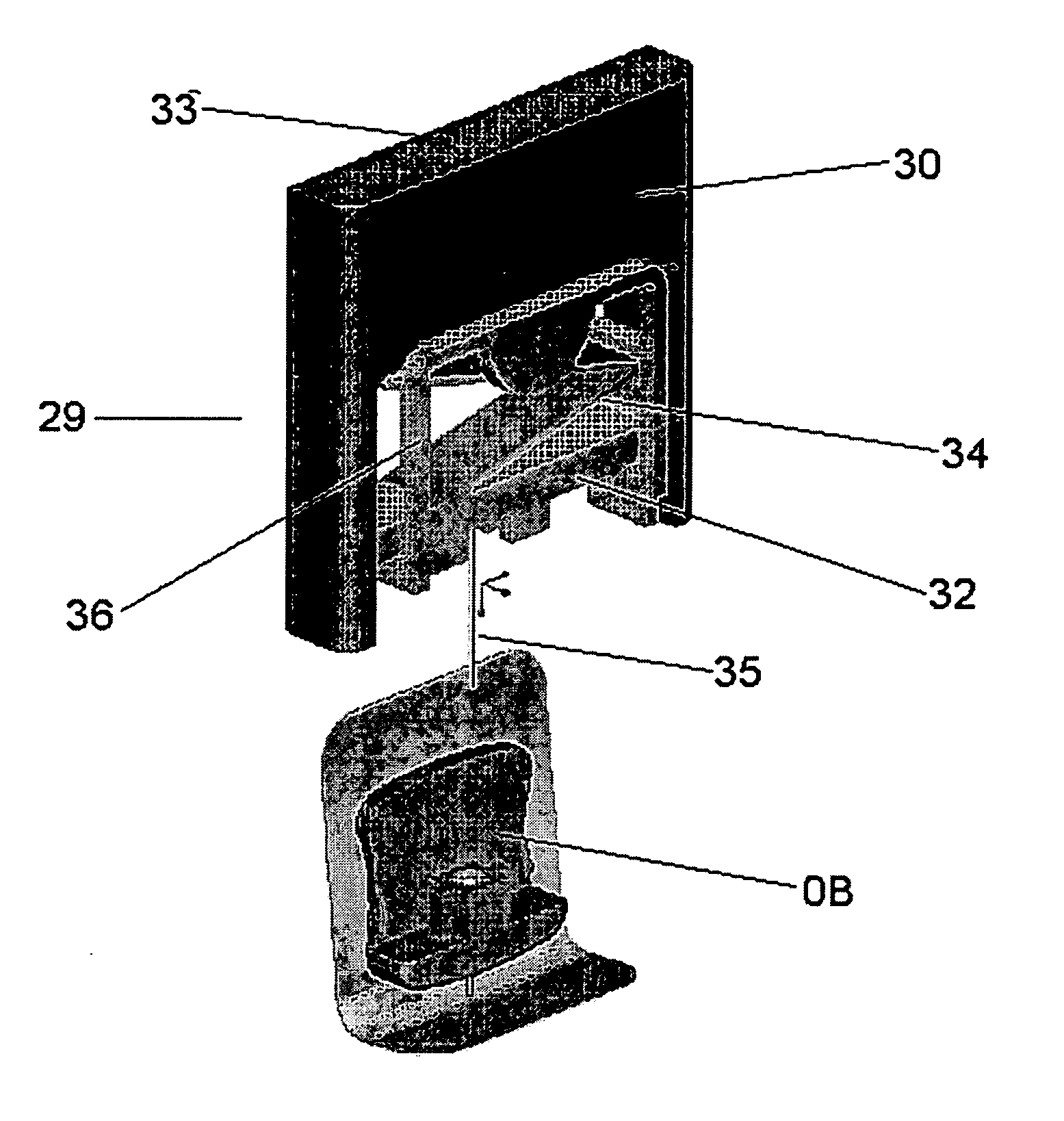
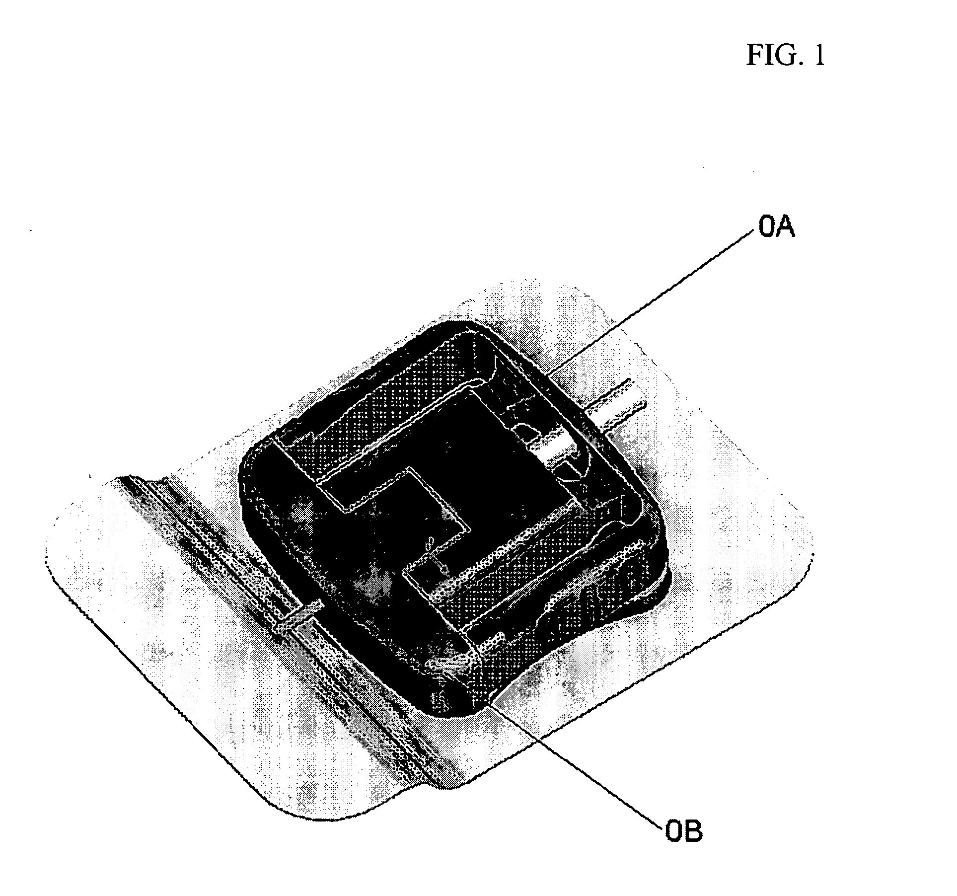
[0095]FIG. 6-11 shows an injector device (29) which can be used for injection of the infusion part (0B) of the infusion set. In FIG. 6 the injector device is separated from the infusion part (0B) and FIG. 7 and 8 show the same injector device (29) joined with an infusion part (0B). The injector device comprises a housing (30) with two longitudinally extending guiding means (31) formed as grooves in this embodiment and a longitudinally slidable member (32) having guiding means (31a), in this embodiment a rim, corresponding to the guiding means (31). A penetrating needle (35) is extending from the front part of the slidable member (32), and the needle (35) is at the end where it is fastened to the slidable member (32) surrounded by guiding means corresponding to the guiding means (13) on the infusion part (0B). The slidable member (32) is capable of moving from a retracted position to a forward position, and is driven from the retracted position to the forward position by a spring (34...

second embodiment

[0097] FIGS. 12 to 17 show the injector device according to the invention where the pivoting member (36) is fastened centrally in relation to the slidable member (32). FIG. 12 shows the injector device in a state where the pivoting member (36) protects the needle prior to injection of the cannula (5) of the infusion part (0B). The figure shows the housing (30) with another type of longitudinally extending guiding means (31), in this case a bar. The housing further has gripping means (40), preferably in the form of recesses, as means for getting a better grip of the injector device.

[0098] Centrally positioned release means (39) is shown on one of the main faces of the injector device. The advantage of a one button release mechanism is that the risk of a slanting injection is reduced.

[0099] In FIG. 13 is shown an injector device prepared for insertion of the needle. The pivoting member is positioned away from the embracing position in an angle v≈90° in relation to the main axis of th...

third embodiment

[0102] In FIG. 21A-D it is shown how the infusion part (0B) along with the slidable member (32) and the spring (34) of the third embodiment fit into the housing (30). The unit (?) shown between the pivoting arm (36) and the insertion part (0B) is an adapter which makes it possible to use a standard injector for different guiding means (13) on the infusion part (0B).

[0103] In FIG. 22A-B is shown fixing means (44) placed on the pivoting member (36). It is possible to temporarily attach a part of the adhesive support (1) to the fixing means in order to secure the position of the adhesive support in such a way that the adhesive surface of the support (1) will be turned towards the skin of the patient. Further release means (39) in the form of two buttons, one on each side of the housing (30), can be seen as well as the protruding stopping tab (43).

[0104]FIG. 23A-B shows in further details and without the housing how the adhesive support (1) is hooked to the fixing means (44) due to at ...


PUM


Abstract

An infusion set having an infusion part for insertion into a patient and a connector for connecting the infusion part with a medical device through a tube is provided. The connector is axially displaceable relative to the infusion part. The infusion part includes an adhesive support, a base part with a first set of guiding means and at least two retention devices for locking the connector to the infusion part, a cannula extending from the base part and being in fluid communication with a cavity. The cavity is further adapted to receive a second cannula extending from the connector where the second cannula is in fluid communication with the tube. The infusion set further includes a second set of guiding means that are adapted to fit with the first set of guiding means and at least two arms. The retention devices extend from an upper surface of a main surface of the base part and the arms include means corresponding to the retention members.

Description

[0001] This application claims priority to Danish Patent Application No. PA 200400493, filed Mar. 26, 2004 and U.S. Provisional Application No. 60 / 556,863, filed Mar. 26, 2004.TECHNICAL FIELD [0002] The invention relates to an infusion set for an intermittent or continuous administration of a therapeutical substance, such as insulin and an injector device for an infusion set. An infusion set comprises an infusion part with a cannula to penetrate the skin of a person and a connector for connecting the infusion part with a medical device preferably a medical delivery device such as an insulin pump. [0003] An infusion set has in its assembled form a substantially planar rear side and a relatively large width compared to its thickness, thus allowing it to lie flat on the patient's skin and thereby minimizing the discomfort of carrying the infusion set. [0004] The infusion part is placed in the patient for a longer and not specified time period while the connector is supposed to be conne...

Claims


Application Information

Patent Timeline
IPC IPC(8): A61M5/158A61M25/16A61M37/00
CPCA61M5/158A61M2005/1587A61M2005/1585A61M37/00A61M5/162A61M5/14A61M5/46
Inventor KORNERUP, GRETEMOGENSEN, LASSE WESSELTOFTGORANSSON, MAGNUS WALTER
Owner UNOMEDICAL AS
Why Eureka
Try Eureka