Method and system for creating a virtual team environment

Inactive Publication Date: 2005-09-29
NORTEL NETWORKS LTD +1
View PDF4 Cites 85 Cited by
  • Summary
  • Abstract
  • Description
  • Claims
  • Application Information

AI Technical Summary

Benefits of technology

[0026] The invention therefore provides a user-friendly, intuitive mechanism that facilitates collaboration among members of a geographically dispersed team. The virtual team environment includes a graphical user interface for displaying dynamic preference and presence information for each member of the team, so that a user has awareness of each of the other team members. The virtual team environment enables the

Problems solved by technology

While there is motivation for people to work together more closely and more effectively due to competitive pressures, the increasing geographical dispersion of talent in the workforce creates a dilemma which is not easily resolved.
Physical collocation in today's business world is not, however, generally practical even when workers are employed by the same company.
As currently available, however, such services are not optimized to facilitate collaboration between team members.
For example, even though modern facilities, such as described in co-applicants' U.S. Pat. No. 6,097,804 which issued Aug. 1, 2000 and is entitled METHOD AND SYSTEM FOR COMPLETING A VOICE CONNECTION BETWEEN FIRST AND SECOND VOICE TERMINALS IN A SWITCHED TELEPHONE NETWORK, facilitate call setup and control by permitting calls to be initiated from a worldwide web interface or the like, problems are still inherent.
It is still impossible to determine the availability of a called party before a call is placed.
Electronic mail tends, however, to be a relatively slow method of communication.
However, no availability information is provided respecting the called party or the disposi

Method used


Image

  • Method and system for creating a virtual team environment
  • Method and system for creating a virtual team environment
  • Method and system for creating a virtual team environment

Examples


Example

[0064] It will be noted that throughout the appended drawings, like features are identified by like reference numerals.

DETAILED DESCRIPTION OF THE PREFERRED EMBODIMENT

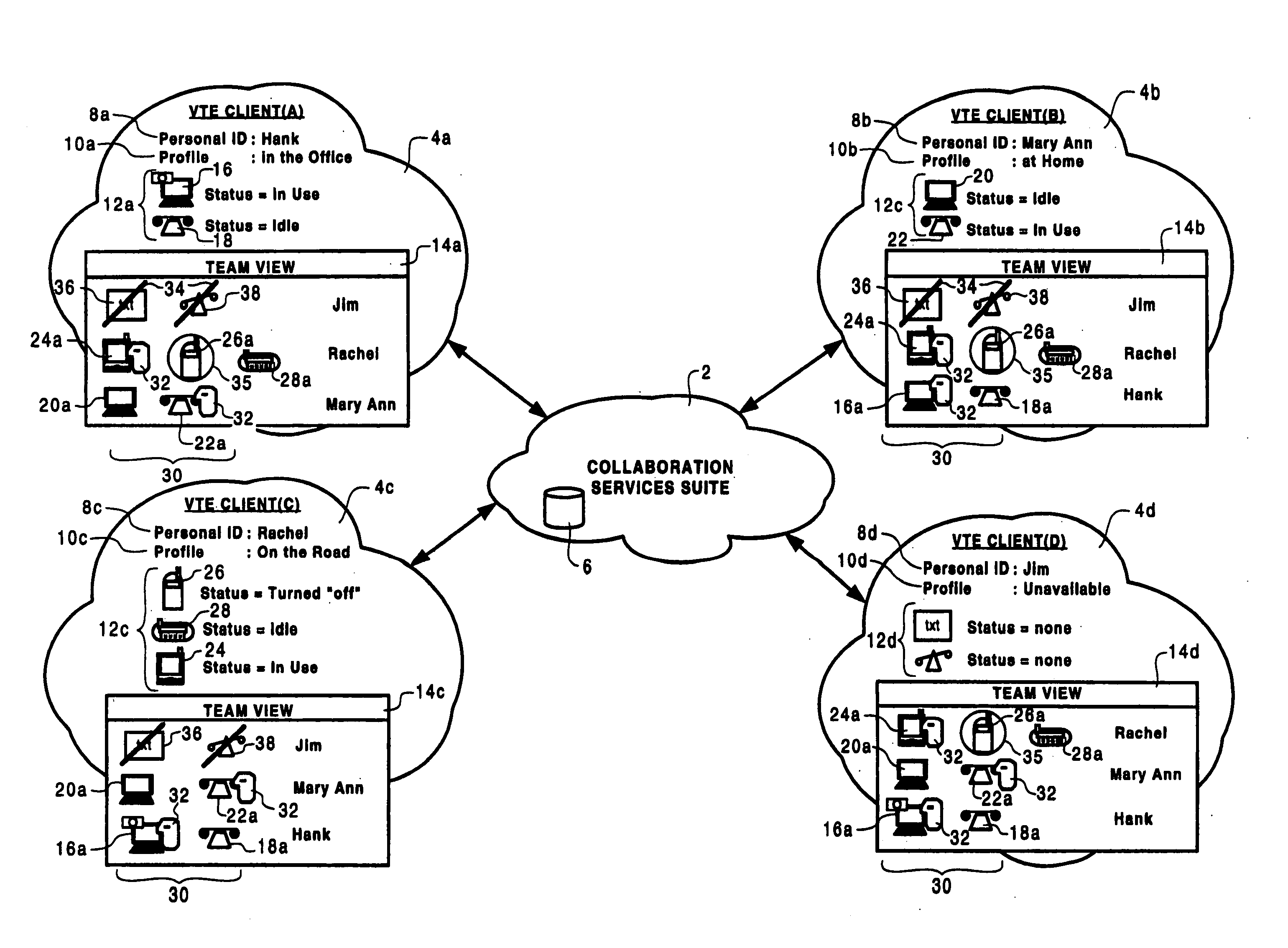
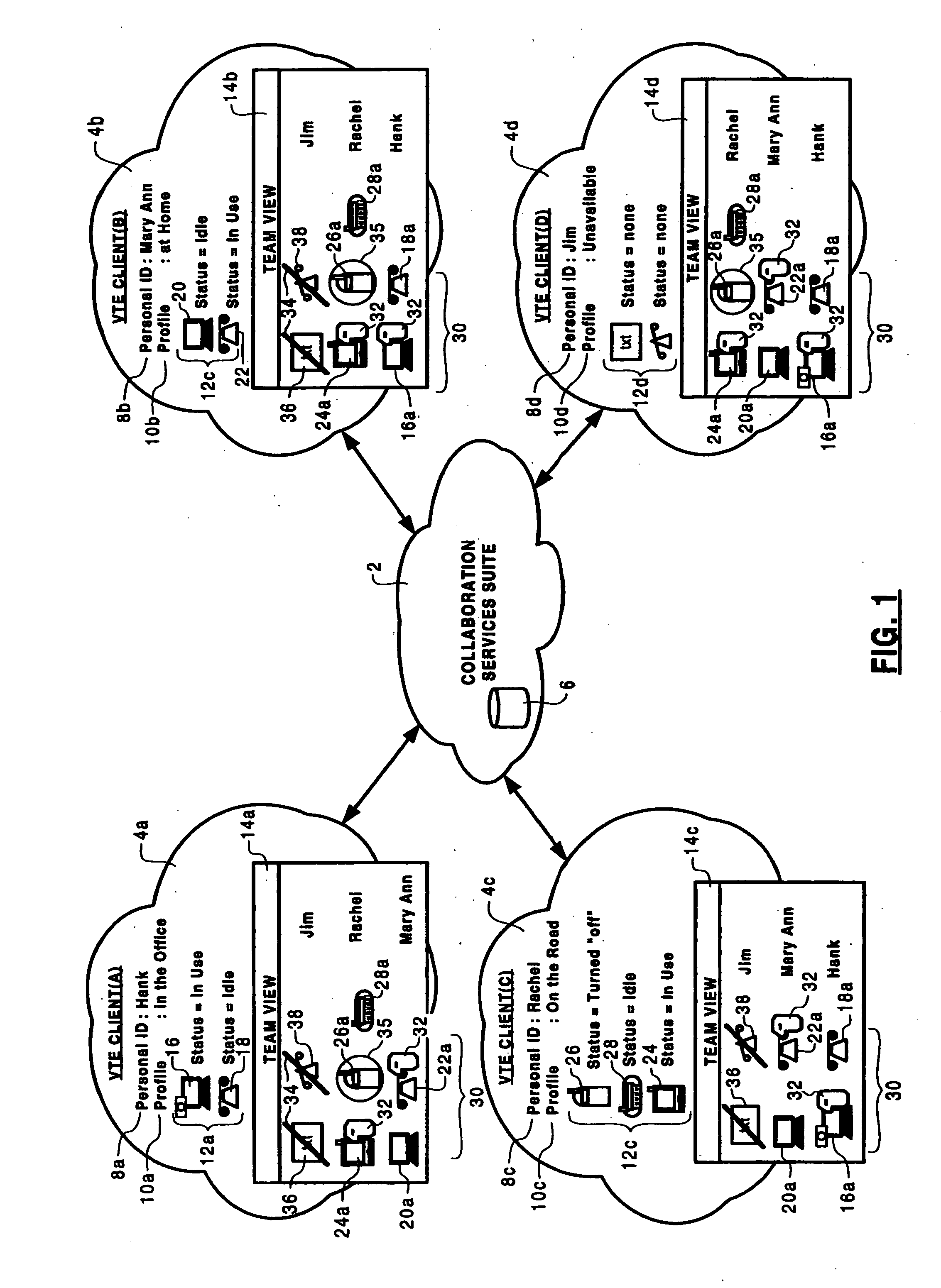
[0065] The present invention provides a collaboration services suite 2 which is designed to instantiate a virtual team environment (VTE) 3 for integrating, in a synergistic manner, a plurality of traditional, emerging, and new communications-related capabilities to facilitate collaboration among geographically dispersed members of a team. As used in this document, the word “team” means any group of interested parties that have a desire to collaborate for business, academic, political or social reasons. Although the description that follows refers specifically to “work teams”, it should be understood that the virtual team environment may be used for many other purposes. For example, the methods and apparatus in accordance with the invention may be used by families, groups of friends, academic institutions, political o...


PUM


Abstract

A collaboration services suite is adapted to support a plurality of integrated telecommunications services accessed by geographically dispersed team members using a virtual team environment (VTE) client that generates a graphical user interface (GUI) for each of the respective team members. Communications sessions are automatically set up by the collaboration services suite in response to request messages generated by the VTE client when a team member initiates a communications session request using the GUI. Team members require no knowledge of another team member's communications device address in order to initiate a communications session. The collaboration services suite includes a VTE server that communicates with the VTE clients, a presence engine that collects and maintains a status of communications devices specified in a current profile of the team member; and, a call server for handling setup and control of a voice component of each communications session completed.

Description

CROSS-REFERENCE TO RELATED APPLICATIONS [0001] This is the first application filed for the present invention. MICROFICHE APPENDIX [0002] Not Applicable. TECHNICAL FIELD [0003] The invention relates in general to work environments and, in particular, to a virtual team environment that facilitates collaboration among geographically-dispersed team members using a distributed application that provides the virtual team environment. BACKGROUND OF THE INVENTION [0004] The knowledge economy is fundamentally affecting the modern work environment. As demand for knowledge workers increases, new work paradigms are being developed in which specialized teams are assembled for specific projects. Those specialized teams may need to work together for a matter of days, weeks or months to accomplish a given project. With more regularity, the team is disbanded after the project is completed and team members move on to other projects, often working with a partly or completely different group of people. ...

Claims


Application Information

Patent Timeline
IPC IPC(8): G06F3/033G06F3/048G06Q10/10H04L12/18H04L12/58H04L29/06H04L29/08H04M3/56H04M7/00
CPCG06F3/0481H04L69/329H04L12/1813H04L12/58H04L12/581H04L29/06H04L51/04H04M3/42374H04M3/567H04M7/003H04M2201/42H04M2203/5018H04M2203/5063H04M2207/20H04L67/36H04L67/24H04L67/306H04L67/14G06Q10/10H04L67/54H04L67/75H04L51/222H04L51/00H04L9/40
Inventor THOMPSON, CHRISTOPHERBEATON, BRIAN F.GROSSNER, CLIFFORD P.LIVERSIDGE, DOUGLAS E.ROMANIUK, ROMANSMITH, COLIN D.R.ZDRALEK, JAMES F.BOUCHARD, JEAN J.FORTIER, STEPHANE F.MERCIER, DENISWILLIAMS, L. LLOYD
Owner NORTEL NETWORKS LTD
Why Eureka
Try Eureka