Barrel accessory rail system

Inactive Publication Date: 2005-10-06
RA BRANDS
View PDF39 Cites 65 Cited by
  • Summary
  • Abstract
  • Description
  • Claims
  • Application Information

AI Technical Summary

Benefits of technology

[0007] The barrel accessory rail system of the present invention provides a simple and easy to use system for rigidly securing a magazine extension or accessory mount to the barrel of a firearm without adversely affec

Problems solved by technology

However, many presently available clamps tend to compress the magazine extension tube, which can potentially impede round capacity and proper function of the weapon.
Additionally,

Method used


Image

  • Barrel accessory rail system
  • Barrel accessory rail system
  • Barrel accessory rail system

Examples


Example

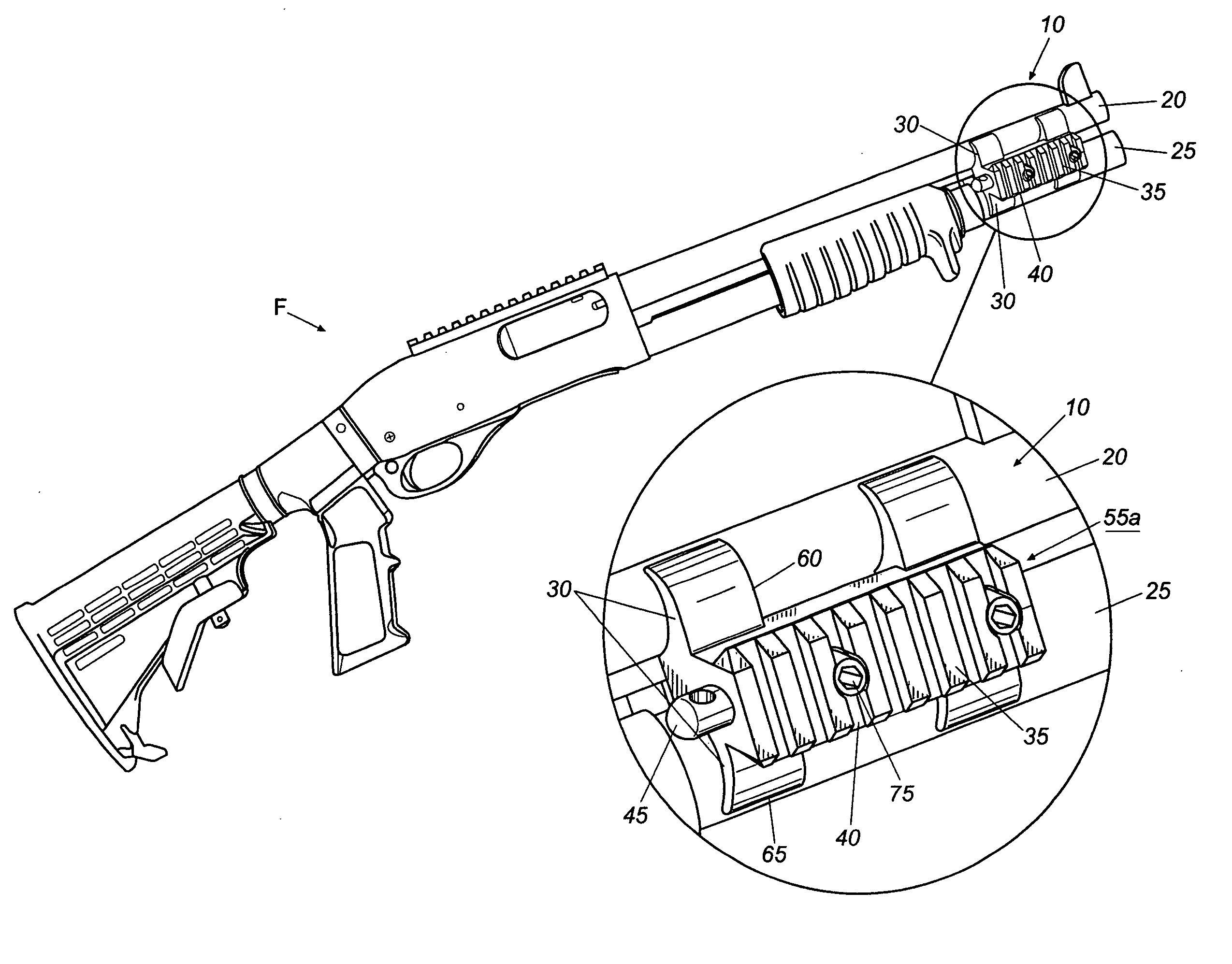
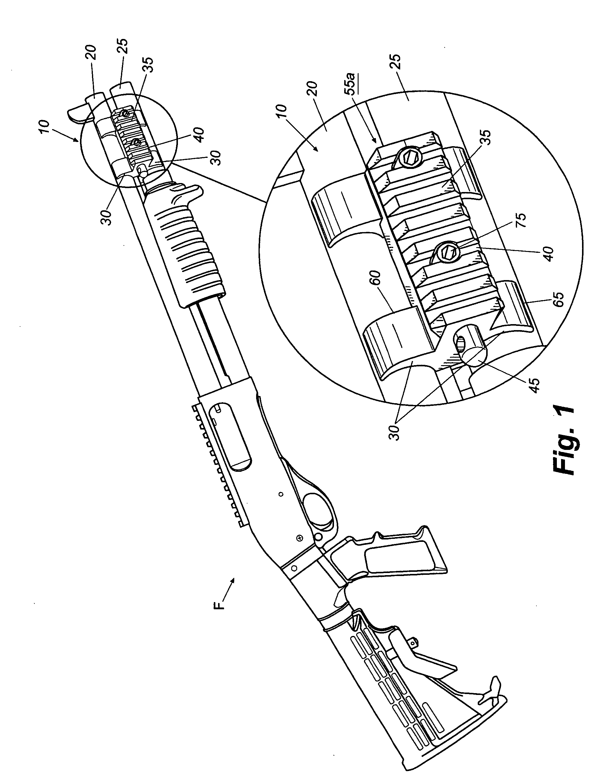
[0021] The present invention generally is directed to a barrel accessory rail system (BARS) for use with a firearm. The BARS typically will be used with a shotgun, rifle, or other long gun, but also may be used other types of firearms, such as a long-barrel pistol or other similar type of hand gun. The BARS of the present invention may be used to clamp a tubular magazine extension to the barrel to maintain the barrel and magazine extension in a secure, rigid alignment. Additionally, the BARS may provide a sling attachment point for the firearm, and may further include features for mounting various firearm accessories, such as flashlights, white lights, laser sights, or IR illuminators or various other tactical options or accessories.

[0022]FIG. 1 depicts generally an exemplary BARS 10 attached to a firearm F, in one example embodiment, a shotgun. The BARS 10 is mounted removably at a forward section 15 of the firearm F, and secures the barrel 20 and the magazine extension 25 in a ri...


PUM


Abstract

A barrel accessory rail system includes a pair of cooperating clamping sections, each including at least one pair of flanges spaced by a transverse rail, and a fastener for securing the pair of opposed clamping sections in clamping engagement with a barrel and magazine extension of a firearm. The flanges are adapted to couple a barrel and a magazine extension to a firearm and permit attachment of accessories to the firearm.

Description

CROSS-REFERENCE TO RELATED APPLICATION [0001] This application claims priority to U.S. Provisional Application Ser. No. 60 / 557,987, filed Mar. 31, 2004, which is incorporated by reference herein in its entirety.FIELD OF THE INVENTION [0002] The present invention generally relates to firearms and, in particular, to a barrel accessory rail system for clamping a magazine extension to the barrel of a firearm, and for providing an attachment point for mounting accessories to the firearm. BACKGROUND OF THE INVENTION [0003] A barrel clamp may be used with a firearm to maintain a tubular magazine extension or accessory mount for the firearm in a secure, rigid alignment with the barrel. However, many presently available clamps tend to compress the magazine extension tube, which can potentially impede round capacity and proper function of the weapon. [0004] Some barrel clamps provide a means for attaching an accessory to the firearm. However, the attaching means often is unique to the manufac...

Claims


Application Information

Patent Timeline
IPC IPC(8): F41A21/08F41C27/00
CPCF41C27/00F41A21/08F41A21/00
Inventor HAUGEN, MICHAELMURPHY, RANDALL
Owner RA BRANDS
Why Eureka
Try Eureka