

Electric brake
a technology of electric brakes and brake pads, applied in the direction of friction linings, mechanical devices, transportation and packaging, etc., can solve the problems of vehicle movement and the inability to release the parking brak
- Summary
- Abstract
- Description
- Claims
- Application Information
AI Technical Summary
Problems solved by technology
Method used
Image

Examples
first embodiment
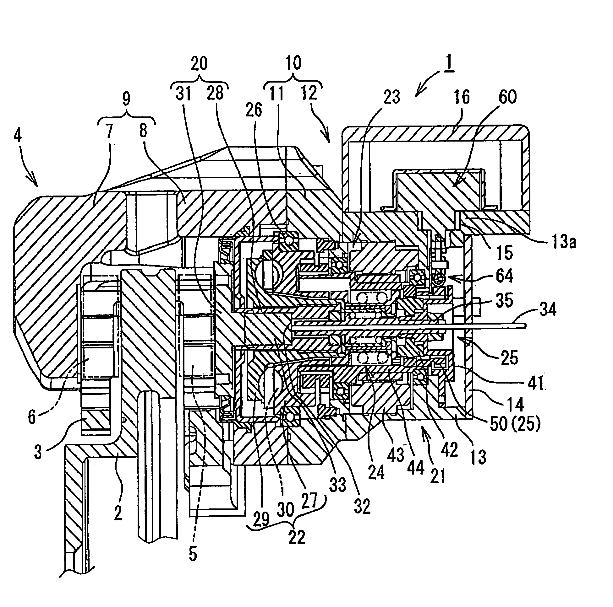
[0038] Referring to FIGS. 1 to 5, an electric brake according to the present invention is described below. In FIGS. 1 to 4, an electric brake 1 comprises a caliper 4 supported by a carrier 3 that is fixed to a non-rotational portion (such as a knuckle) of a vehicle body on an inner side of the vehicle body relative to a disc rotor 2. The caliper 4 is supported in a state such that it Is capable of a floating movement in an axial direction of the disc rotor 2. A pair of brake pads 5 and 6 are disposed so as to face each other with the disc rotor 2 being provided therebetween. The brake pads 5 and 6 are supported by the carrier 3 in such a manner as to allow a movement of the brake pads 5 and 6 in the axial direction of the disc rotor 2.
[0039] The caliper 4 comprises a claw member 9 and a caliper body 10 connected to the claw member 9. The claw member 9 includes a claw portion 7 formed on a forward end thereof and an annular base body 8 formed on a basal end thereof. The claw portion ...
second embodiment
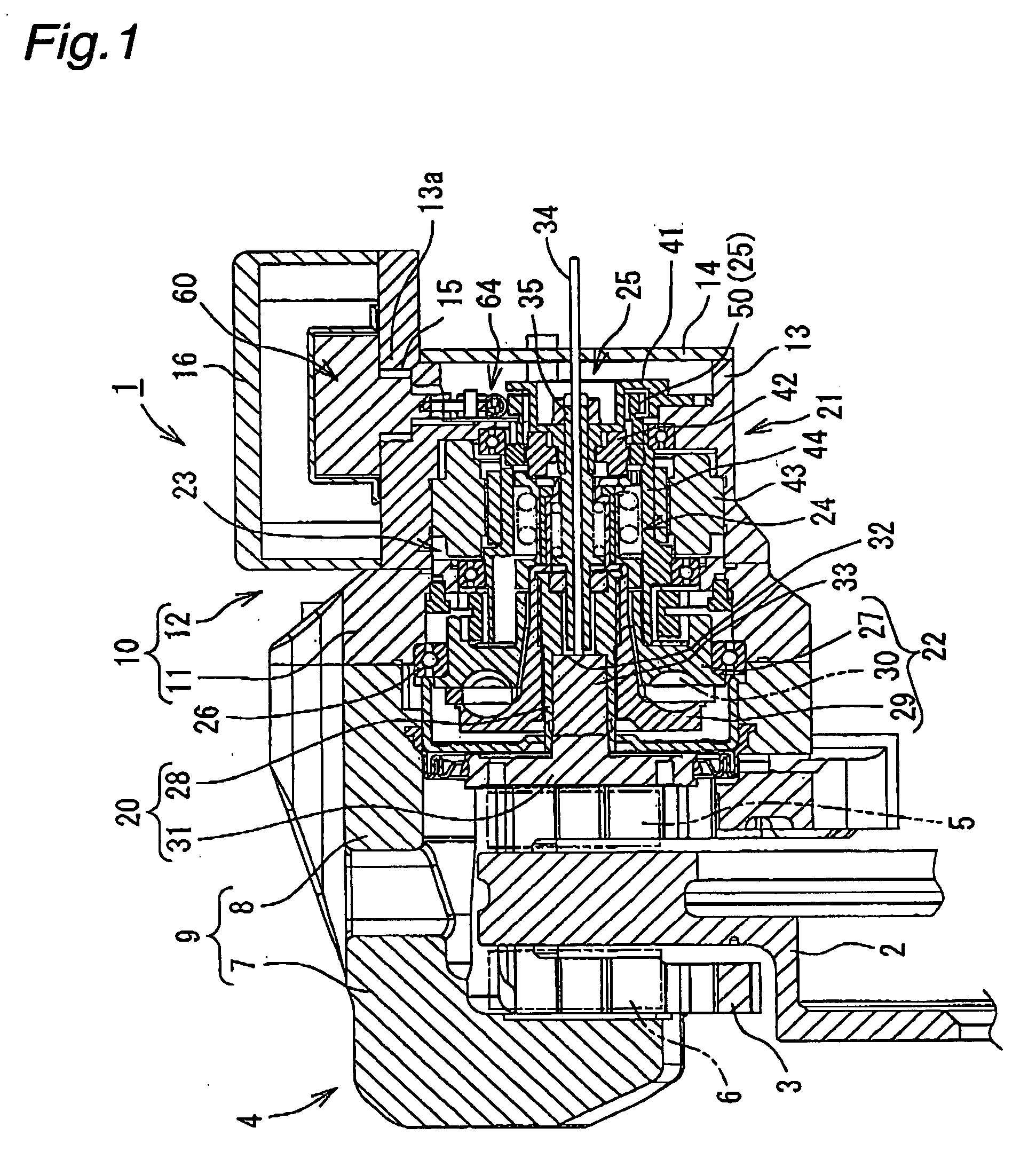
[0077] In the electric brake 1A in the second embodiment, when the parking brake mechanism 25A is operated [when the parking brake is applied (namely, the engaging pawl portion 133 of the engaging plunger body 130 is engaged with the tooth portion 57)], if the supply of current to the coil 67 becomes impossible due to breaking of the cable 126 (see FIG. 2) or the like, an emergency action to release the parking brake can be conducted manually by using the tool 122A.
[0078] That is, the tool 122A is inserted into the bolt hole 120 in the obliquely upward direction and the forward end portion 124A is abutted against the lower surface of the manual release receiving portion 132. In this state, when the other end portion of the tool 122A exposed to the outside is pivotally moved about the bolt hole 120 in a downward direction, the manual release receiving portion 132 (that is, the engaging plunger body 130) is moved in an upward direction in FIG. 7, by means of the forward end portion 12...
third embodiment
[0084] In the electric brake 1B in the third embodiment, when the parking brake mechanism 25B is operated [when the parking brake is applied (namely, the engaging pawl portion 142 of the engaging pivot arm body 140 is engaged with the tooth portion 57)], if the supply of current to the coil 67 becomes impossible due to breaking of the cable 126 (see FIG. 2) or the like, an emergency action to release the parking brake can be conducted manually by using the tool 122B.
[0085] That is, as indicated in FIG. 9, the tool 122B is inserted into the bolt hole 120 in an upward direction until a forward end portion (a tool forward end portion 124B) of the tool 122B abuts against the forward end portion 141b of the pivot arm portion 141. The tool 122B is further inserted in the axial direction of the bolt hole 120. Accordingly, the forward end portion 141b of the pivot arm portion 141 (and hence the engaging pivot arm body 140) is pushed in an upward direction in FIG. 9. According to this moveme...
PUM
 Abstract
Description
Claims
Application Information