Filter

a filter and filter body technology, applied in the field of filters, can solve the problems of blocking up and dissolving and achieve the effect of reducing the number of dollops of bird faeces in the water

Inactive Publication Date: 2005-10-06
SCOTTIES INVENTIONS & IDEAS CONSULTANCY
View PDF6 Cites 6 Cited by
  • Summary
  • Abstract
  • Description
  • Claims
  • Application Information

AI Technical Summary

Benefits of technology

[0015] The component of fluid flow across the upstream surface of a filter element (as distinct from through the filter element) thus results in the filter being self-cleaning to some extent.

Problems solved by technology

These filters have a number of disadvantages, including that they block up and that the dollops of bird faeces dissolve in the water.

Method used


Image

  • Filter
  • Filter

Examples


Embodiment Construction

Construction

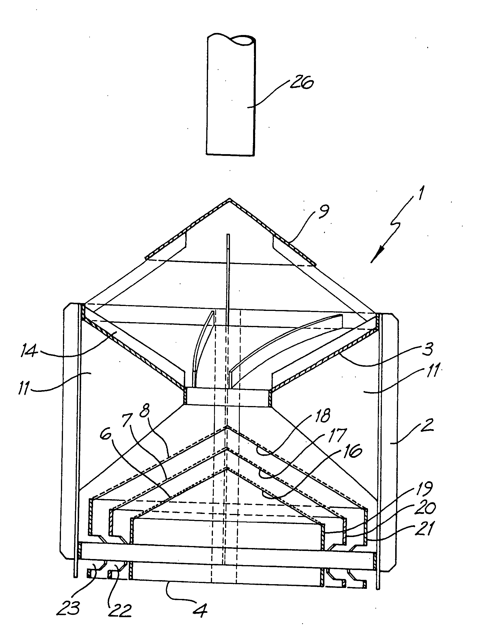
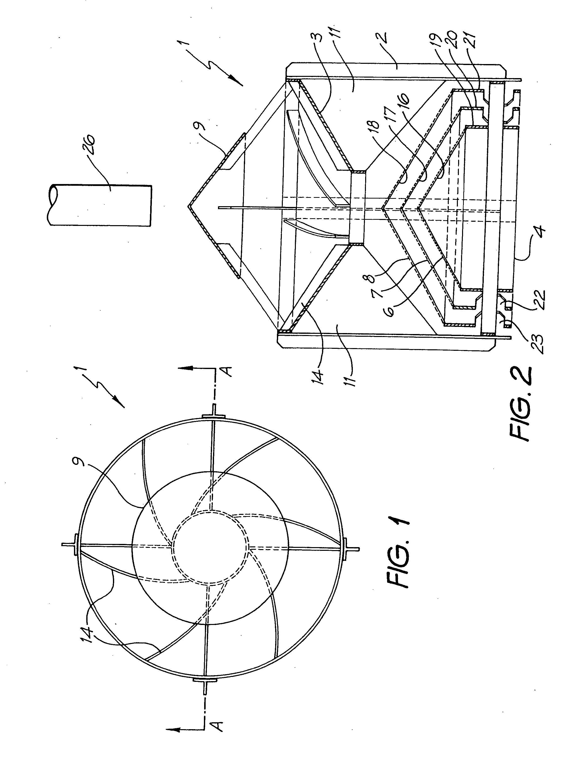
[0018] Apparatus 1 according to one embodiment of the present invention is illustrated in FIGS. 1 and 2. The apparatus 1 includes three separate conical filter elements 6, 7 and 8, each of which filter elements is supported on top of a support element 16, 17 and 18 respectively. Each of the support elements 16, 17 and 18 includes a substantially conical portion for location of a filter element, which conical portion is in turn mounted on a substantially cylindrical portion 19, 20 and 21 respectively.

[0019] In the present embodiment, it is especially preferred that the surface of the conical filter elements 6, 7 and 8 are each orientated at an angle of 35° to the base of the cone. In this embodiment the cones are mounted with a clearance of 25 mm between each filter element and the conical support above it. According to this embodiment, the uppermost filter element 8 has a 1 mm mesh, the middle filter element 7 has a 50 micron mesh and the lowermost filter element 6 ha...


PUM

PropertyMeasurementUnit
angleaaaaaaaaaa
angleaaaaaaaaaa
angleaaaaaaaaaa

Abstract

A filter includes three separate conical filter elements each of which is supported on top of a support element. Each of the support elements has a substantially conical portion for location of a filter element. The conical portion is in turn mounted on a substantially cylindrical portion. The surfaces of the conical filter elements are each preferably orientated at an angle of 35° to the base of the cone and each filter element preferably mounted with a clearance of 25 mm between it and the conical support. The uppermost filter element preferably has a 1mm mesh, the middle filter element preferably has a 50 micron mesh and the lowermost filter element preferably has a 1 micron mesh. The middle and outermost cylindrical portions have apertures through them adjacent their open ends. A funnel is mounted above and substantially co-axial with the filter elements. The inner surface of the funnel carries a series of or ridges which extend arcuately inwards and downwards within the funnel in the anti-clockwise direction (for operation in the Southern hemisphere) when viewed from the inlet end of the funnel. A distributor cone is mounted above the funnel, with the axis substantially co-axial with the axes of the funnel and the filter elements and with its periphery terminating within the catchment area of the funnel.

Description

BACKGROUND OF THE INVENTION [0001] 1. Field of the Invention [0002] The present invention relates to filters, and various embodiments of it are particularly suitable as a rainwater filter. [0003] 2. Background Art [0004] There are a number of environments which require the filtration of solid material from a fluid flow. Examples include the filtration of metal cuttings from cutting oil used in conjunction with machine tools, and the filtration of solid materials from rain water. [0005] Rainwater tanks that are in use in Australia generally receive water through a concave strainer which has a mesh of about 1 mm (that is, about 1,000 microns). Such a strainer acts as a simple primary filter which traps leaves, twigs, large solids and dollops of bird faeces. [0006] These filters have a number of disadvantages, including that they block up and that the dollops of bird faeces dissolve in the water. The water stored in the rainwater tank is thus high in bird faecal coliform count. SUMMARY...

Claims


Application Information

Patent Timeline
Patent Type & Authority Applications(United States)
IPC IPC(8): B01D29/50B01D29/58
CPCB01D29/58B01D2201/02B01D29/904B01D29/908
Inventor SCOTT-SMITH, BRUCE
Owner SCOTTIES INVENTIONS & IDEAS CONSULTANCY
Why Eureka
Try Eureka