Brake booster vacuum prediction algorithm and method of use therefor

a technology of brake booster and vacuum prediction algorithm, which is applied in the direction of brake system, electric control, machine/engine, etc., can solve the problems of increased cost per vehicle, insufficient brake booster vacuum to meet vehicle braking requirements, and even higher cost per vehicle, so as to improve the vacuum in the intake manifold

Inactive Publication Date: 2005-10-06
GM GLOBAL TECH OPERATIONS LLC
View PDF4 Cites 29 Cited by
  • Summary
  • Abstract
  • Description
  • Claims
  • Application Information

AI Technical Summary

Benefits of technology

[0008] In a second preferred embodiment of the present invention, vehicle input parameters are, at least, manifold absolute pressure (MAP), atmospheric pressure, and vehicle speed, all of which being available from the main engine controller or engine control module (ECM). Vehicle speed is used to determine vehicle deceleration by which the occurrence of a brake event can be determined. Brake booster vacuum is repeatedly predicted or estimated through repeated calculations utilizing known and calculated vehicle parame

Problems solved by technology

When the reduced intake manifold vacuum is such that the brake booster vacuum exceeds a calibrated brake booster vacuum threshold (that is the absolute pressure of the brake booster vacuum is higher than the absolute pressure of the brake booster vacuum threshold), it could theoretically result in inadequate brake booster vacuum to meet vehicle braking requirements and engine operation must be modified to provide adequate intake manifold vacuum to meet brake booster vacuum requirements for vehicle braking

Method used


Image

  • Brake booster vacuum prediction algorithm and method of use therefor
  • Brake booster vacuum prediction algorithm and method of use therefor
  • Brake booster vacuum prediction algorithm and method of use therefor

Examples


Embodiment Construction

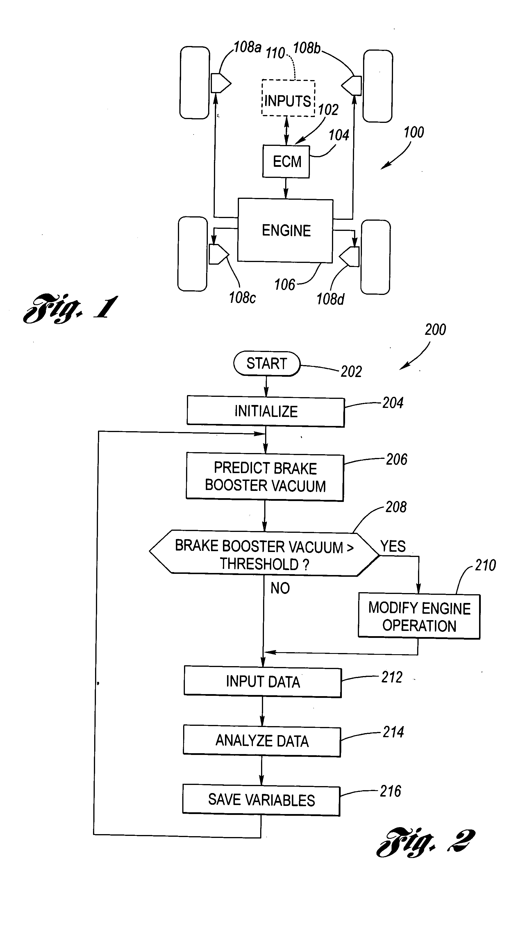
[0019] Referring now to the Drawings, FIG. 1 is a schematic representation of a motor vehicle brake system 100. The brake booster vacuum prediction algorithm according to the present invention 102 resides, preferably, within the engine control module (ECM) 104. The ECM 104 controls the operation of the vehicle engine 106 and, through intake manifold vacuum 106V, the brake booster vacuum of the brake booster 112 providing brake pedal 116 assist to the master cylinder for actuation of the brakes 108a, 108b, 108c, 108d of the vehicle. External vehicle inputs 110 may be provided to the ECM 104 for purposes of operation of the present invention.

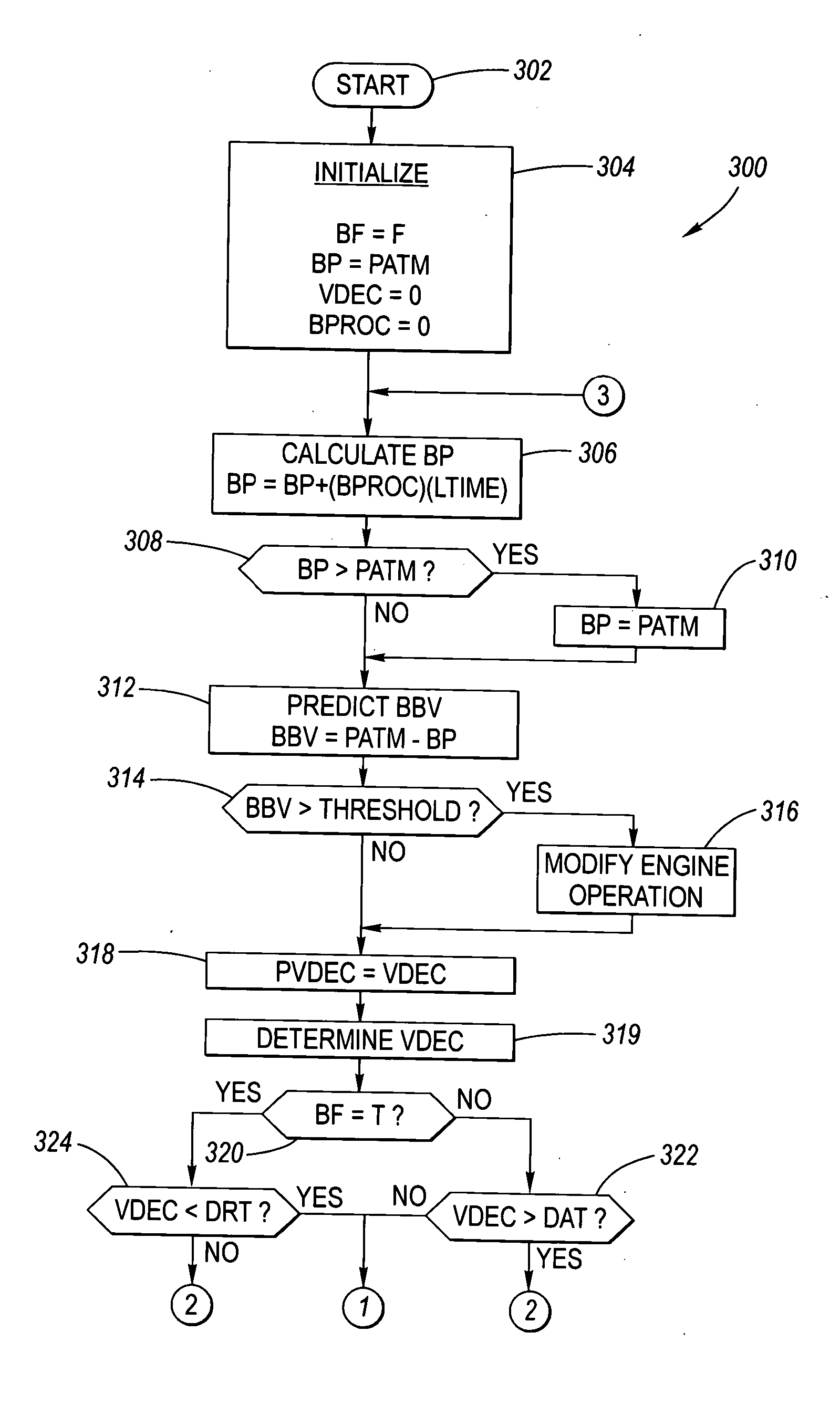
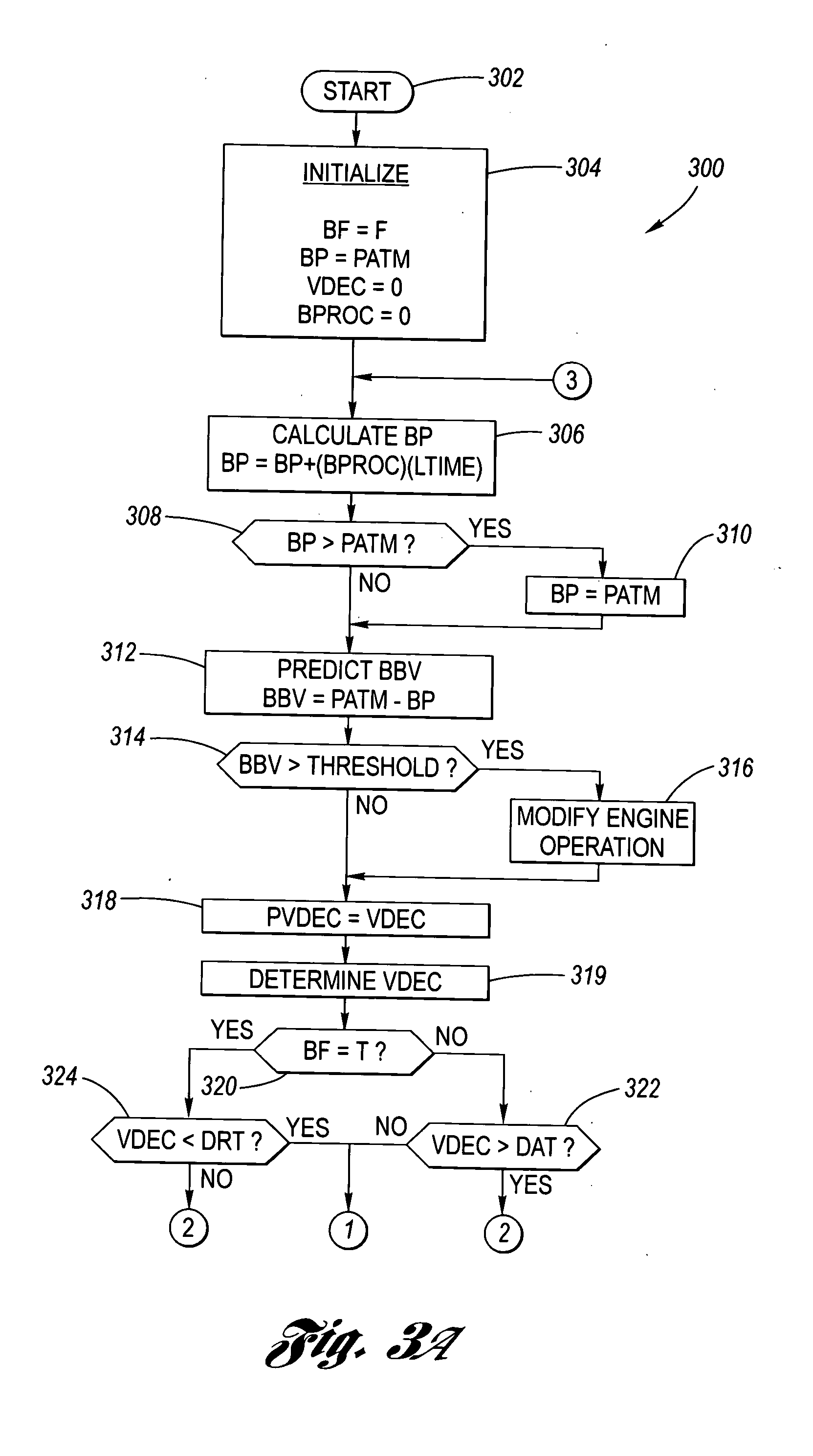
[0020]FIG. 2 is an overview flow chart algorithm 200 of the brake booster vacuum prediction algorithm according to the present invention. The algorithm 200 starts at Block 202 through the main engine controller or ECM then control passes to Block 204 where initialization of variables and parameters occurs. Brake booster vacuum is then predicted a...


PUM


Abstract

An algorithm residing in, for example the ECM of a motor vehicle, which predicts brake booster vacuum for vehicles using vacuum for brake pedal assist. The predicted brake booster vacuum is compared to a calibrated brake booster vacuum threshold to determine if adequate brake booster vacuum is available to meet vehicle braking requirements, whereupon engine operation can be modified, as necessary, to improve intake manifold vacuum such that brake booster vacuum requirements for vehicle braking are better satisfied.

Description

TECHNICAL FIELD [0001] The present invention relates to motor vehicles and, more particularly, to motor vehicles with brake boosters using vacuum for brake pedal assist. BACKGROUND OF THE INVENTION [0002] Most engines on motor vehicles with brake boosters using vacuum (brake booster vacuum) for brake pedal assist utilize the engine intake manifold as a vacuum source for the brake booster to provide sufficient brake booster vacuum to meet vehicle braking requirements. [0003] Some engines now use Displacement on Demand, which deactivates cylinders when load requirements are low, and / or use variable valve timing and / or other engine controls that can affect brake booster vacuum. These technologies improve fuel economy by reducing intake manifold vacuum (that is, the absolute pressure of the intake manifold increases) in order to reduce pumping losses. When the reduced intake manifold vacuum is such that the brake booster vacuum exceeds a calibrated brake booster vacuum threshold (that i...

Claims


Application Information

Patent Timeline
IPC IPC(8): B60T8/44B60T13/72B60T17/22
CPCB60T13/72B60T2201/03B60T17/22F02D41/021F02D2250/41
Inventor COLLINS, JAMES F.NISONGER, ROBERT L.MURPHY, CHRISTOPHER P.
Owner GM GLOBAL TECH OPERATIONS LLC
Why Eureka
Try Eureka