RET for optical maskless lithography

a technology ret, which is applied in the field of optical maskless lithography, can solve the problems of long acceptance cycle, high cost, and high cost of new equipment and modifications of old equipmen

Active Publication Date: 2005-10-06
MICRONIC LASER SYST AB
View PDF39 Cites 61 Cited by
  • Summary
  • Abstract
  • Description
  • Claims
  • Application Information

AI Technical Summary

Problems solved by technology

Because manufacturing batches are very valuable and manufacturing processes are sensitive to even small mistakes, semiconductor device manufacturing is a conservative business.
Qualification cycles and standards for new equipment and modifications of old equipment are lengthy and demanding.
However, the acceptance cycle is most challenging.

Method used


Image

  • RET for optical maskless lithography
  • RET for optical maskless lithography
  • RET for optical maskless lithography

Examples


Embodiment Construction

[0043] The following detailed description is made with reference to the figures. Preferred embodiments are described to illustrate the present invention, not to limit its scope, which is defined by the claims. Those of ordinary skill in the art will recognize a variety of equivalent variations on the description that follows.

Introduction

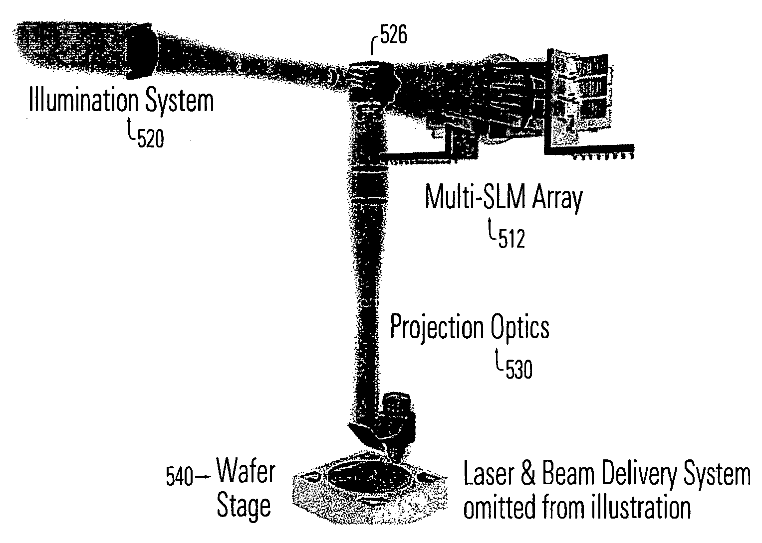
[0044] For low-volume runs, Optical Maskless Lithography (OML) provides an attractive alternative for mask-based lithography due to ever-increasing reticle costs. Foundries and ASIC fabs are finding that reticles are an increasingly dominating part of their manufacturing costs, especially for small series production. Optical Maskless Lithography provides a cost-effective alternative while maintaining process compatibility with existing fab technologies.

[0045] An Optical Maskless Scanner with a wavelength of 193 nm and 0.93 NA for resolution compatible with the 65 nm node is achievable. A throughput of 5 wph (300 mm) is desired.

[0046] The spatial...


PUM

PropertyMeasurementUnit
wavelengthaaaaaaaaaa

Abstract

The present invention relates to Optical Maskless Lithography (OML). In particular, it relates to providing OML with a recognizable relationship to mask and phase-shift mask techniques.

Description

RELATED APPLICATION [0001] This provisional application claims the benefit of and incorporates by reference U.S. Provisional application No. 60 / 547,614 by Torbjörn Sandstrom, entitled “RET for Optical Maskiess Lithography” filed on 25 Feb. 2004 and U.S. Provisional application No. 60 / 552,598 by Torbjörn Sandstrom and Hans Martinsson, entitled “RET for Optical Maskless Lithography (OML)” filed on 12 Mar. 2004. [0002] Incorporated by reference to illustrate the technology applied in this application are several previously filed applications. These include: U.S. Provisional application Nos. 60 / 415,509, entitled “Resolution Extensions in the Sigma 7000 Imaging SLM Pattern Generator” by inventors Torbjörn Sandström and Niklas Eriksson, filed on 1 Oct. 2002; No. 60 / 444,417, entitled “Further Resolution Extensions for an SLM Pattern Generator” by inventors Torbjörn Sandstrom and Niklas Eriksson, filed on 3 Feb. 2003; and No. 60 / 455,364, entitled “Methods and Systems for Process Control of ...

Claims


Application Information

Patent Timeline
Patent Type & Authority Applications(United States)
IPC IPC(8): G02B26/00G03F1/00G03F7/20
CPCG03F1/26G03F7/70291G03F7/70283G03F7/2057
Inventor SANDSTROM, TORBJORNMARTINSSON, HANS
Owner MICRONIC LASER SYST AB
Why Eureka
Try Eureka