Arrangement and a mehtod for clamping thin rods

a technology of arrangement and clamping rod, which is applied in the direction of large fixed members, instruments, vices, etc., can solve the problems of reducing the efficiency of the apparatus, requiring a considerable amount of removal, and requiring substantial amount of work, so as to reduce the risk of applying torsional stress and improve the efficiency of the arrangement

Active Publication Date: 2005-10-06
NYFORS TEKNOLOGI
View PDF11 Cites 6 Cited by
  • Summary
  • Abstract
  • Description
  • Claims
  • Application Information

AI Technical Summary

Benefits of technology

[0008] By arranging said substantially V-groove in a movable clamping member of said first clamping means and not in one being fixed to a framework of the apparatus, it will be easy to remove the first clamping member for exchanging it by another first clamping member having a groove being differently designed or for replacing a first clamping member being worn out or dama

Problems solved by technology

Undue intrusion of the blade into the fibre during the cleaving process can damage the fibre so as to detract from the quality of the resulting end surfaces.
This exchange takes in the apparatus according to U.S. Pat. No. 4,790,465 a considerably long period of time resulting in substantially costs as a consequence of a reduced efficiency of the apparatus.
The reason for this is that a considerably amount of work is required for removing said first clamping member from

Method used


Image

  • Arrangement and a mehtod for clamping thin rods
  • Arrangement and a mehtod for clamping thin rods
  • Arrangement and a mehtod for clamping thin rods

Examples


Embodiment Construction

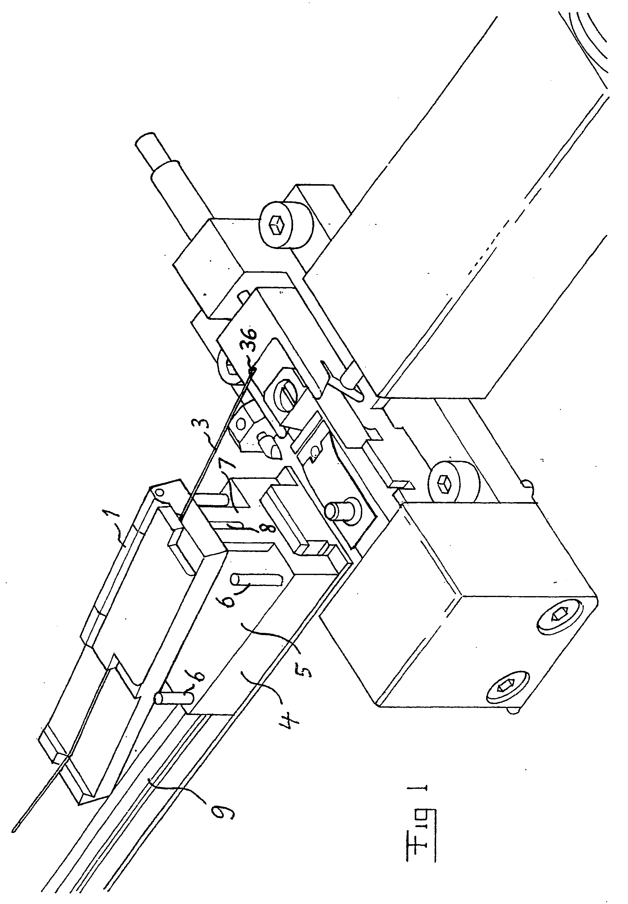
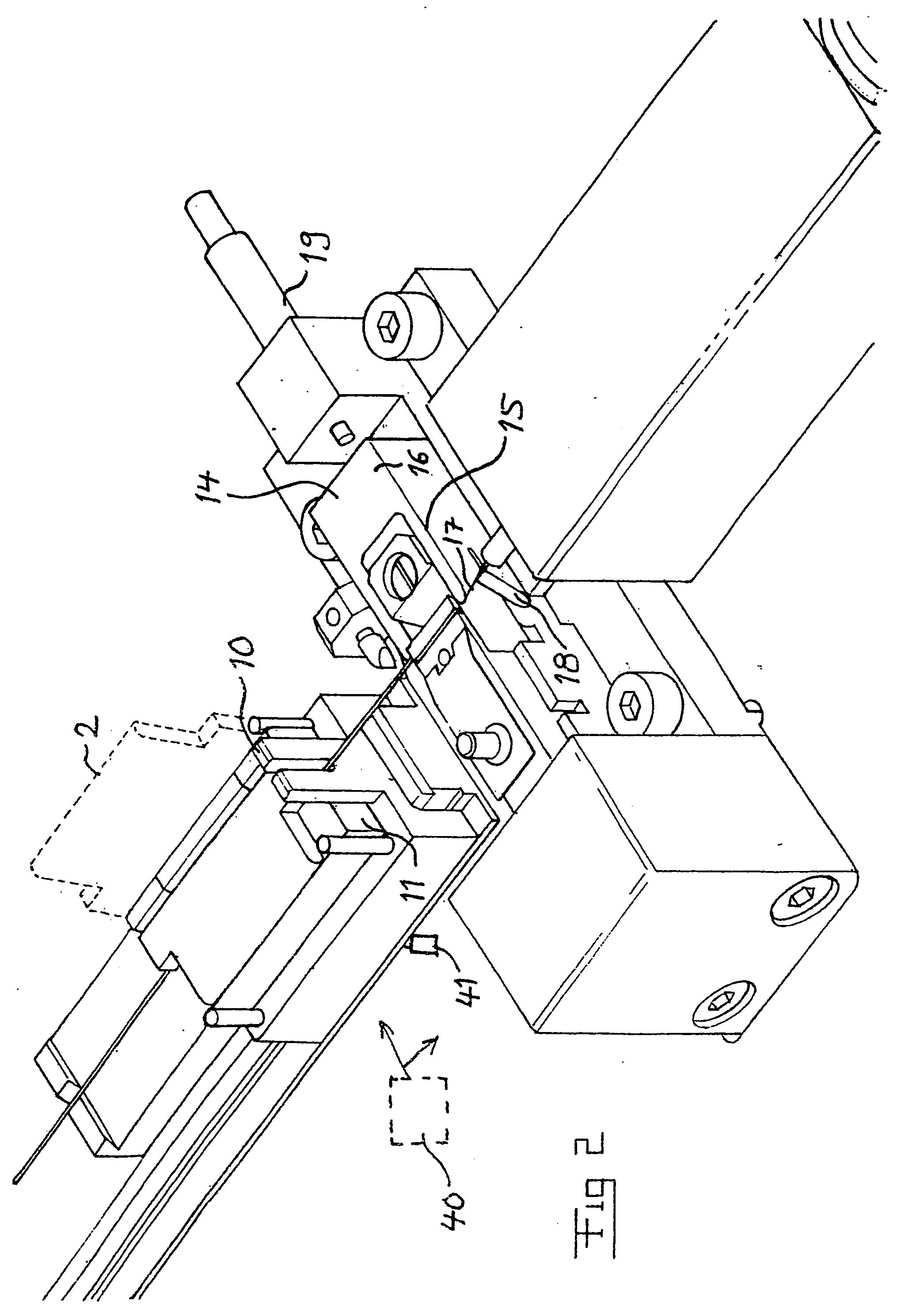
[0031]FIG. 1 illustrates an apparatus for cleaving thin rods of glass or quartz, preferably optical fibres, having a diameter below 1 mm, and preferably in the range of 50 μm-200 μm. The optical fibre is clamped in a second clamping means 1 in the form of a conventional fibre holder used for holding a fibre also when joining two optical fibres, and this is already known. It is schematically illustrated in FIG. 2 by dashed lines how a lid 2 of said clamping means may be pivoted for opening and closing this clamping means. This clamping means 1 is adapted to hold the fibre to be cleaved with a part 3 on which the cleaving is to be carried out projecting out from the fibre holder.

[0032] The apparatus also comprises a member 4 adapted to receive the fibre holder 1 therein for holding it in a well-defined position during the cleaving sequence. The receiving member 4 has the character of a carriage with a bottom 5 onto which the fibre holder is intended to rest and guiding members 6 in t...


PUM

PropertyMeasurementUnit
Lengthaaaaaaaaaa
Diameteraaaaaaaaaa
Diameteraaaaaaaaaa

Abstract

An arrangement for clamping thin rods of glass or quartz having a diameter below 1 mm in two mutually-spaced clamping locations for holding a said rod extended between the two clamping locations. The arrangement also comprises first clamping means arranged to clamp the rod in a first clamping location. The first clamping means has a first clamping member (22) with a clamp face (23) of substantially V-groove type for receiving the rod in the groove (24). The first clamping member is movably arranged with respect to a framework (45) of the apparatus for clamping a rod.

Description

TECHNICAL FIELD OF THE INVENTION AND PRIOR ART [0001] The present invention relates to an arrangement for clamping thin rods of glass or quartz (silica) having a diameter below 1 mm as well as a method for carrying out such a clamping according to the preambles of the appended independent arrangement and method claims. [0002] Such an arrangement may be used to clamp and hold most varying types of rods for many different purposes, for instance an optical fibre for stripping or washing the fibre or for cleaving thereof. Although the invention is in general directed to clamping such thin rods of glass or quartz for any purpose, the invention and the problem to be solved thereby will hereinafter by way of a non-limitative example be discussed for the case of clamping optical fibres to be cleaved. [0003] Optical fibre ends are commonly prepared for a variety of purposes (jointing, characterization etc) by a process known as cleaving. In such a process, a blade prepared from a hard materi...

Claims


Application Information

Patent Timeline
IPC IPC(8): G02B6/25
CPCY10T29/53961G02B6/25Y10T225/30Y10T83/5669
Inventor BOTTCHER, UWE
Owner NYFORS TEKNOLOGI
Why Eureka
Try Eureka