Liquid dispensing valve and method with improved stroke length calibration and fluid fittings

a technology of liquid dispensing valves and valve bodies, applied in liquid transferring devices, liquid handling, instruments, etc., can solve the problems of length adjustment mechanisms, time-consuming nozzle changes, and increased inventory of parts

Active Publication Date: 2005-10-13
NORDSON CORP
View PDF8 Cites 34 Cited by
  • Summary
  • Abstract
  • Description
  • Claims
  • Application Information

AI Technical Summary

Problems solved by technology

However, nozzle changes are time consuming and require increased inventory of parts.
In the past, such stroke length adjustment mechanisms have had various drawbacks, for example, related to complexity of use and design, and repeatability of proper adjustments.
Unfortunately, threading a fluid fitting into place can result in inconsistent seal compression from one valve to another and this can result in leakage.
Also, threaded fittings may be prone to the formation of cavities in which liquid stagnation may occur and this can be a problem especially in applications requiring aseptic conditions.
Finally, threaded fittings may not be as easily modified to connect, for example, to a wide variety of push-on type flexible tubing, and may not be easily cleaned as may be necessary for certain applications, including aseptic applications.

Method used


Image

  • Liquid dispensing valve and method with improved stroke length calibration and fluid fittings
  • Liquid dispensing valve and method with improved stroke length calibration and fluid fittings
  • Liquid dispensing valve and method with improved stroke length calibration and fluid fittings

Examples


Embodiment Construction

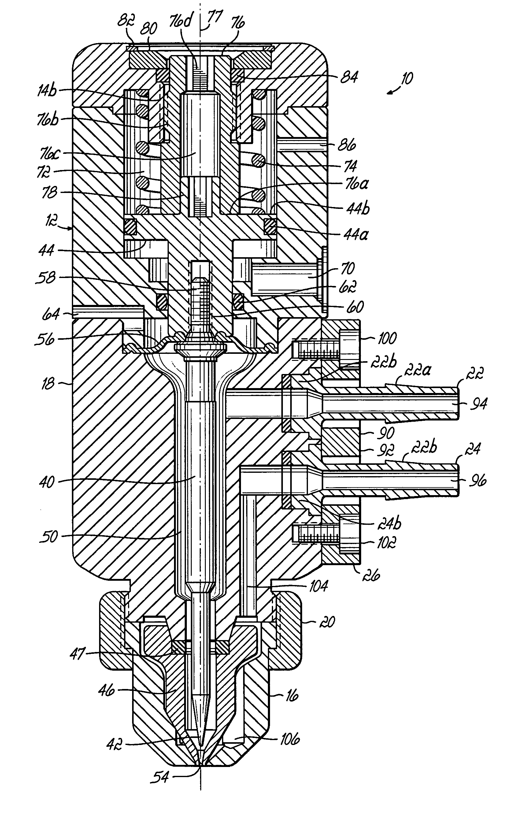
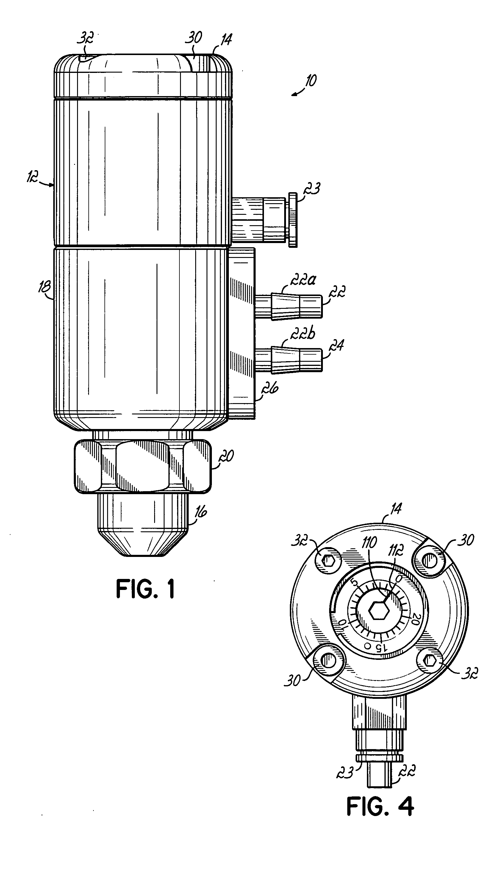
[0014] Referring toFIG. 1, one illustrative example of the invention is embodied in a liquid dispensing valve 10 having a valve body 12 generally comprising a cap 14 at an upper end, a nozzle 16 at a lower end, and a central body portion 18. Nozzle 16 may be retained on central body portion 18 by a threaded nut 20. Fluid fittings 22, 24 are provided for respectively supplying liquid and process air to valve body 18. In the preferred embodiment, fittings 22, 24 include barbed portions 22a, 24a which receive push-on type flexible conduits, such as silicone tubing. Another fluid fitting 23 is used to supply actuation air as will also be discussed below. Fluid fittings 22, 24 are retained on valve body 18 by a clamp plate 26 in a manner to be described further below. Cap 14 is retained on central body portion 18 by, for example, cap screws 30, 32 (FIG. 4).

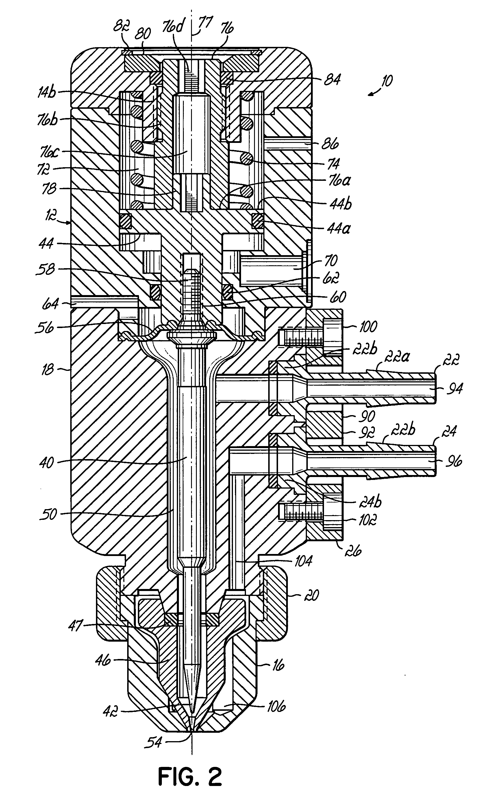
[0015] Referring now to FIGS. 2 and 3, which respectively show the open and closed positions of dispensing valve 10, a reciprocating...


PUM


Abstract

A liquid dispensing valve includes a valve body, a valve seat, and a reciprocating valve member engageable with the valve seat for controlling flow through a liquid outlet. A calibration device includes a rotatable stroke control stop member and a rotatable reference ring. The reference ring and stop member may be initially rotated to a zero position and, subsequently, the stop member may be rotated to set the desired stroke length. One or more fluid fittings are provided and sealed against the valve body using a clamp plate.

Description

FIELD OF THE INVENTION [0001] The present invention generally relates to fluid dispensing devices and methods related to dispensing liquids with or without process air assistance and, more specifically, to adjusting liquid flow through the liquid outlet and making connections to the air and liquid passages within the valve. BACKGROUND OF THE INVENTION [0002] Liquid dispensing valves of the type associated with the present invention generally provide for the selective flow of fluid, such as liquid with or without process air, through a valve body and then out of a nozzle orifice or liquid outlet. The process air may impart some characteristic to the liquid discharging from the nozzle orifice, such as swirling or otherwise moving a liquid filament, or atomizing the liquid as it is discharged. Control of the flow through the nozzle orifice is typically effected by reciprocating a valve member along a stroke length. The valve member ordinarily seats against a valve seat member which inc...

Claims


Application Information

Patent Timeline
Patent Type & Authority Applications(United States)
IPC IPC(8): B05B1/30B67D7/22B05B7/06B05B7/12B05C5/02B67D7/42B67D7/56
CPCB05B1/306B05B7/066B05C5/0225B05B7/1263
Inventor STRONG, WARREN N.VIDAL, MICHAEL A.
Owner NORDSON CORP
Why Eureka
Try Eureka