Developer bearing body and image forming apparatus

a technology of developing rollers and bearings, applied in the field of developing roller bearings and image forming apparatuses, can solve the problems of filming and hardening of the developing roller surface, and achieve the effect of preventing filming

Active Publication Date: 2005-10-13
OKI ELECTRIC IND CO LTD
View PDF3 Cites 19 Cited by
  • Summary
  • Abstract
  • Description
  • Claims
  • Application Information

AI Technical Summary

Benefits of technology

[0006] An object of the present invention is to provide a developer bearing body and an image forming apparatus capable of preventing a filming.
[0009] With such an arrangement, the hardness of the resilient layer and the hardness of the surface layer can be kept in suitable ranges, with the result that the occurrence of the filming can be prevented.

Problems solved by technology

However, if the surface of the developing roller is processed or coated, there is a possibility that the surface of the developing roller may be hardened, depending on the condition of processing or coating (for example, a kind or an amount of material to be used) of the developing roller.
If the surface of the developing roller is excessively hard, the pressure between the developing roller and contact members (i.e., the developing blade, the toner supply roller and the photosensitive drum) may increase, with the result that a filming may occur.

Method used


Image

  • Developer bearing body and image forming apparatus
  • Developer bearing body and image forming apparatus
  • Developer bearing body and image forming apparatus

Examples


embodiment 1

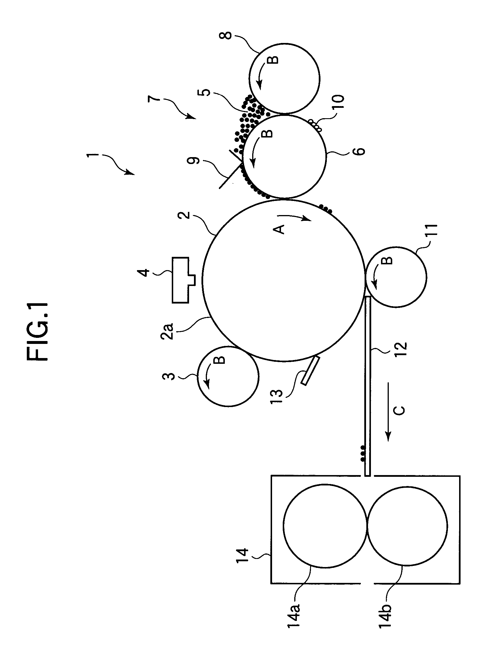
[0018]FIG. 1 is a sectional view of a main part of an image forming apparatus 1 having a developing roller as a developer bearing body according to Embodiment 1 of the present invention.

[0019] In FIG. 1, a photosensitive drum (i.e., a latent image bearing body) 2 is mounted on a not shown chassis together with a driving motor 37 (FIG. 2). The photosensitive drum 2 is rotated by the driving motor 37 in the direction indicated by an arrow A. Along the circumference of the photosensitive drum 2, a charging roller 3, an LED (Light Emitting Diode) head 4, and a developing roller 6 are arranged in this order in the rotational direction of the photosensitive drum 2. The charging roller 3 uniformly charges the peripheral surface 2a of the photosensitive drum 2. The LED head 4 irradiates the peripheral surface 2a of the photosensitive drum 2 with the image light, to form a latent image. The developing roller (i.e., the developer bearing body) 6 supplies a toner (i.e., a developer) 5 to the ...

embodiment 2

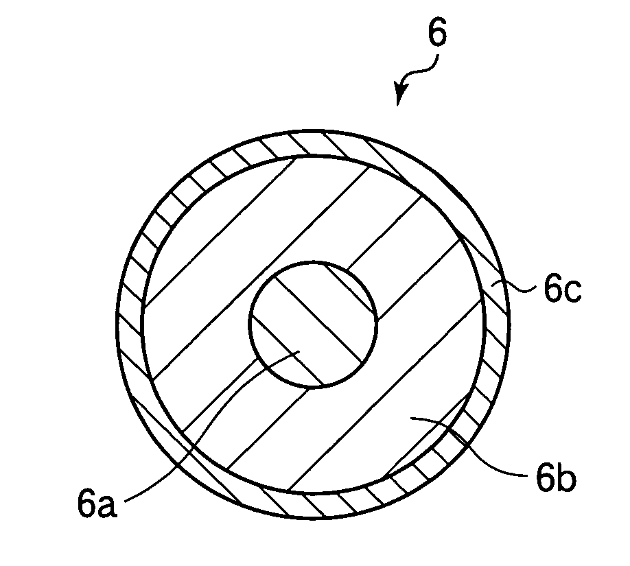
[0047]FIG. 6 is a sectional view showing an internal structure of a developing roller as a developer bearing body according to Embodiment 2 of the present invention.

[0048] The developing roller 51 can be mounted in the image forming apparatus 1 (FIG. 1) instead of the developing roller 6 (FIG. 1) of Embodiment 1. In this case, components of the image forming apparatus 1 other than the developing roller 51 are the same as those described in Embodiment 1. With regard to the components similar to those in Embodiment 1, the duplicated explanation is omitted. The emphasize of the description is laid on the difference between Embodiments 1 and 2.

[0049] As shown in FIG. 6, the developing roller 51 has a core 51a (i.e., a rotation axis) made of metal, a resilient layer 51b (whose electric resistance is adjusted by dispersing a suitable amount of an electrical conductive material therein) formed around the core 51a, and a surface layer 51c formed on the surface of the resilient layer 51b. ...


PUM


Abstract

In an electrophotographic image forming apparatus, a contact-type developing roller contacts a photosensitive drum, a developing blade, a supply roller or the like. If the surface of the developing roller is excessively hard, there is a possibility that a pressure applied between the developing roller and the photosensitive drum or the like may increase, and may cause a filming, i.e., a phenomena in which a toner is degraded and welded to the surface of the developing roller. The filming can be prevented when a JIS-A hardness HA (degree) of a resilient layer of the developing roller and a dynamic hardness HS (mN / μm2) of a surface layer of the developing roller satisfy the following relationship: HA×HS<15.

Description

BACKGROUND OF THE INVENTION [0001] This invention relates to an image forming apparatus (such as a copier or a printer) using electrophotographic technology, and more particularly to a developer bearing body used in a developing device of the image forming apparatus. [0002] Conventionally, an image forming apparatus (such as a printer or a copier) is configured to form an image on a recording medium by electrophotographic processes. In a charging process, a photosensitive drum is charged. In an exposing process, a latent image is formed on the photosensitive body according to image data. In a developing process, the latent image on the photosensitive drum is developed (visualized) with toner. In a transferring process, the developed toner image is transferred to a recording medium such as a paper. In a fixing process, the toner image is fixed to the recording medium by means of heat and pressure. [0003] In such an electrophotographic image forming apparatus, the size of a printable ...

Claims


Application Information

Patent Timeline
Patent Type & Authority Applications(United States)
IPC IPC(8): G03G15/08
CPCG03G15/0818
Inventor EBE, TAKAAKI
Owner OKI ELECTRIC IND CO LTD
Why Eureka
Try Eureka