
Pump diaphram rupture detection

a diaphragm and pump technology, applied in the direction of engine diaphragms, positive displacement liquid engines, liquid fuel engines, etc., can solve the problems of wear and failure of each layer independently

Inactive Publication Date: 2005-10-13
WANNER EGINEERING INC
View PDF13 Cites 4 Cited by
  • Summary
  • Abstract
  • Description
  • Claims
  • Application Information

AI Technical Summary

Benefits of technology

The solution effectively detects diaphragm failures before they propagate, allowing for timely shutdown and preventing contamination, thus making hydraulically driven pumps more suitable for applications that require contamination-free operation.

Problems solved by technology

Although the layers may be bonded to each other, in a preferred embodiment the layers are independently movable relative to each other so that wear and fail of each layer occurs independently.

Method used


Image

  • Pump diaphram rupture detection
  • Pump diaphram rupture detection
  • Pump diaphram rupture detection

Examples


Embodiment Construction

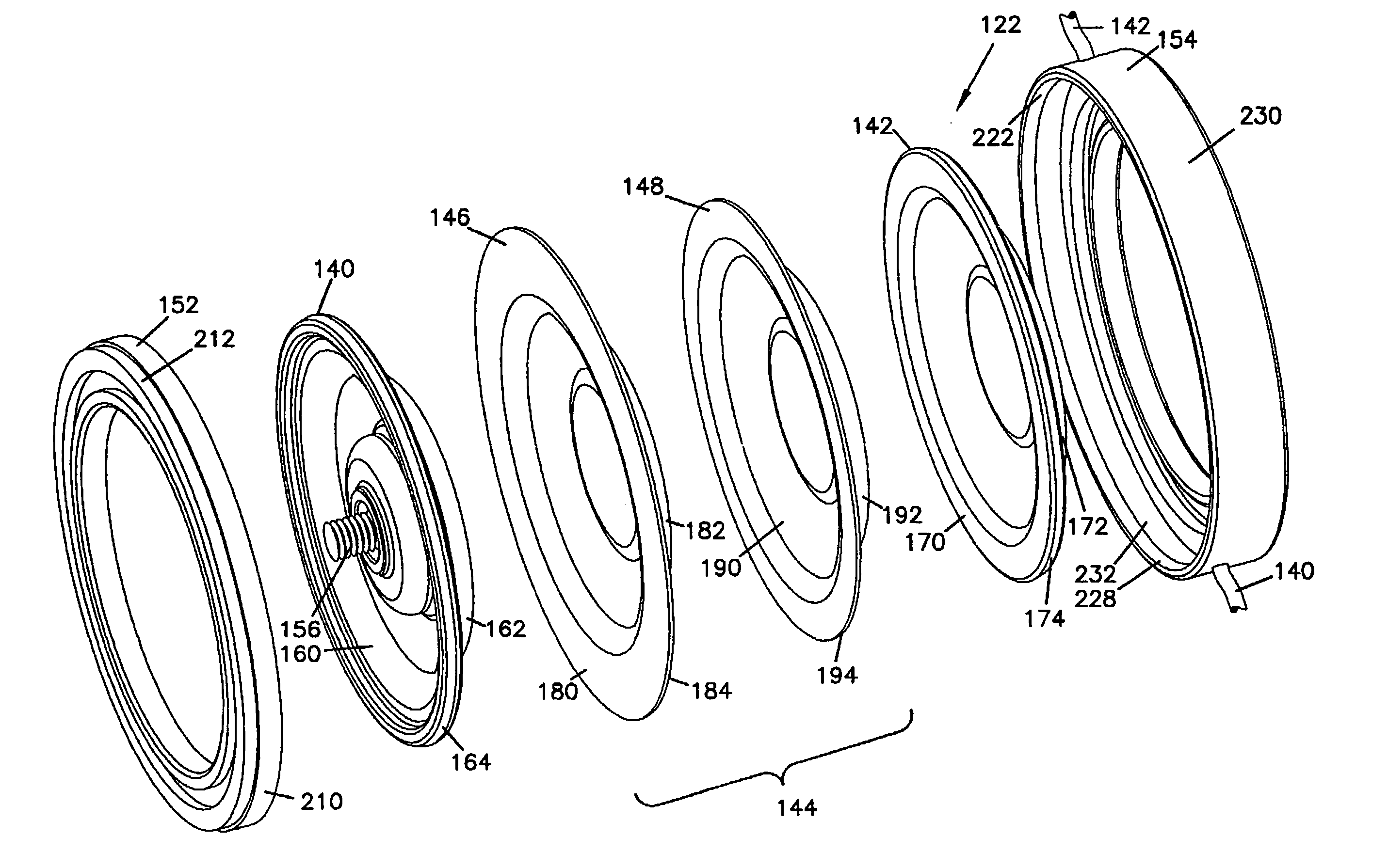
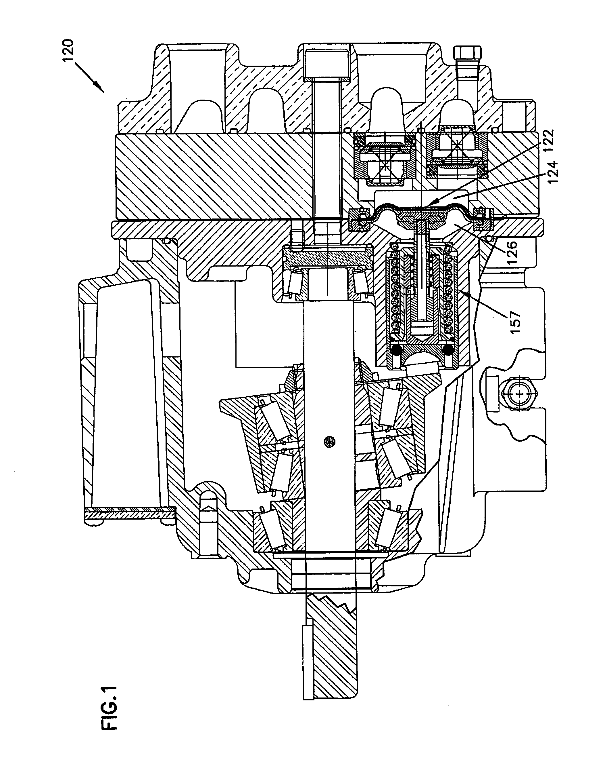
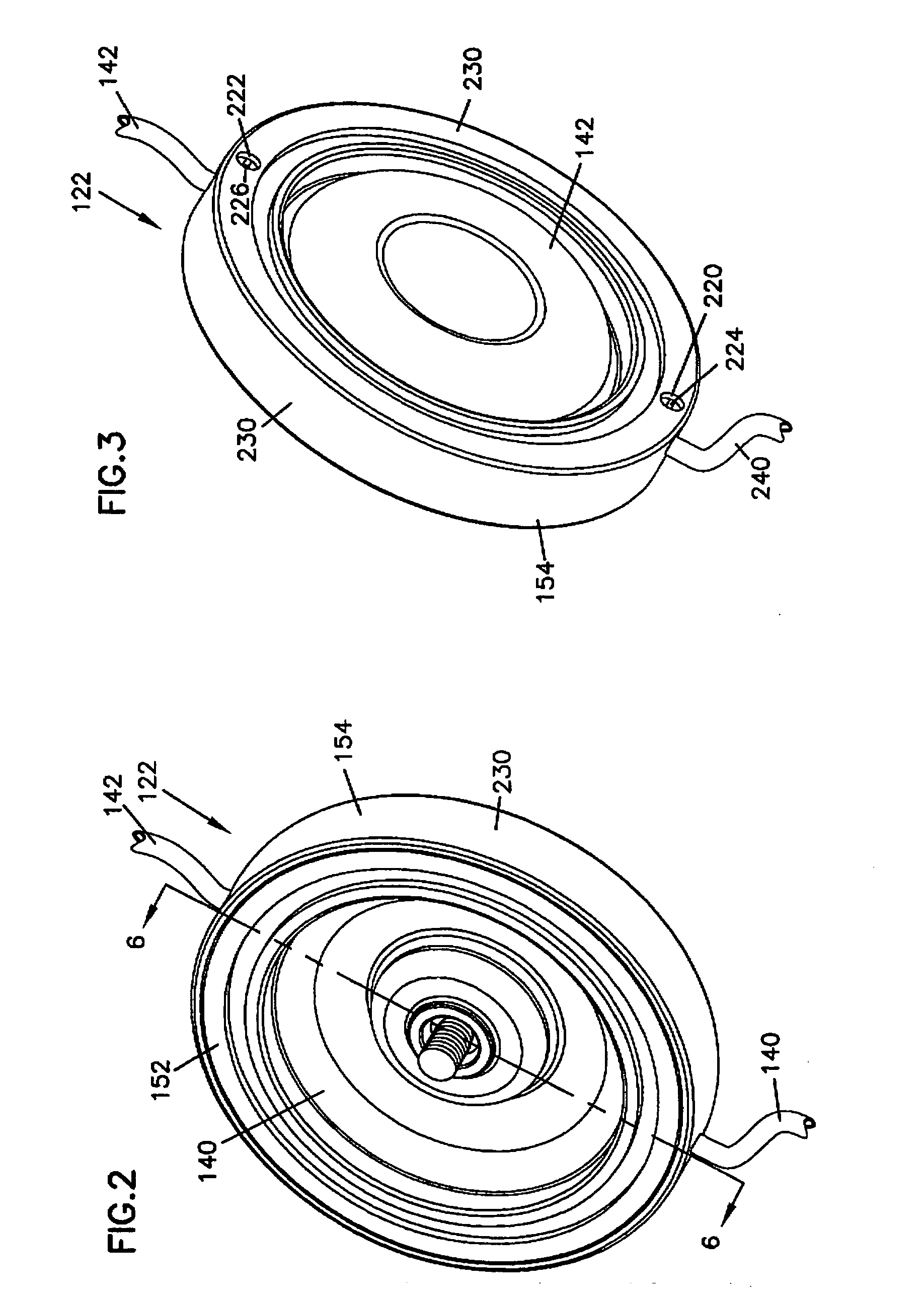
[0041] The present invention generally relates to a diaphragm for a hydraulically driven pump that is an improvement to the conventional diaphragms described above. Like parts are designated by like numerals. Improved parts are distinguished and described. The invention generally relates to hydraulically driven pumps, and more specifically relates to diaphragms for hydraulically driven pumps and the detection of failure in such diaphragms. The diaphragm includes at least three elastomeric layers made of high strain resistant materials. The layer positioned between the other two layers includes a conductive trace embedded therein. Changes in the conductive trace resistance is monitored while the diaphragm is in use. When the resistance values reach a certain predetermined level that indicates failure in one or more of the diaphragm layers, or the possibility of a failure occurring, a failure signal is generated. A rupture of the middle layer will also be detected since a break in the...


PUM


Abstract

A hydraulically driven pump includes a first chamber exposed to a process fluid, a second chamber configured to retain a hydraulic fluid, and a multi-layer diaphragm positioned between the first and second chambers. The diaphragm includes a first layer in contact with the process fluid being pumped, a second layer in contact with the hydraulic fluid, and a third layer that includes an elastomeric base material and an elastomeric conductive trace embedded in the elastomeric base material. The third layer is positioned between the first and second layers and being movable relative to the first and second layers. Changes in an electrical resistance of the conductive trace indicate a failure condition in one of the first, second and third layers.

Description

[0001] This application is a continuation of U.S. application Ser. No. 10 / 726,984, filed Dec. 2, 2003.BACKGROUND OF THE INVENTION [0002] 1. Technical Field [0003] The invention generally relates to hydraulically driven pumps, and more specifically relates to diaphragms for hydraulically driven pumps. [0004] 2. Related Art [0005] The known rotary-operated, oil-backed / driven diaphragm pump is a high-pressure pump inherently capable of pumping many difficult fluids because in the process fluid, it has no sliding pistons or seals to abrade. The diaphragm isolates the pump completely from the surrounding environment (the process fluid), thereby protecting the pump from contamination. [0006] In general, a diaphragm pump 20 is shown in FIGS. 9 and 10. Pump 20 has a drive shaft 22 rigidly held in the pump housing 24 by a large tapered roller bearing 26 at the rear of the shaft and a small bearing (not shown) at the front of the shaft. Sandwiched between another pair of large bearings (not s...

Claims


Application Information

Patent Timeline
Patent Type & Authority Applications(United States)
IPC IPC(8): F04B43/00F04B43/067F16J3/02
CPCF04B43/0054F16J3/02F04B43/067F04B43/009
Inventor HEMBREE, RICHARD D.
Owner WANNER EGINEERING INC
Learn More